Diagnosing an insufficient heat complaint
The Glitch:
Figure 1 is photo sent to me for a “diagnosis.” It shows part of a floor heating system in a commercial building located in a cold climate. The manifold station serves eight circuits of 5/8” PEX tubing. The copper piping supplying the manifold station is 3/4” size. Water temperature to the supply manifold is regulated by a thermostatic mixing valve. There’s a flo-check valve at the top of the copper piping assembly. Flow appears to be created by a small zone circulator. The insulated horizontal piping makes a “U-turn” just to the left of the risers from the floor circuits.
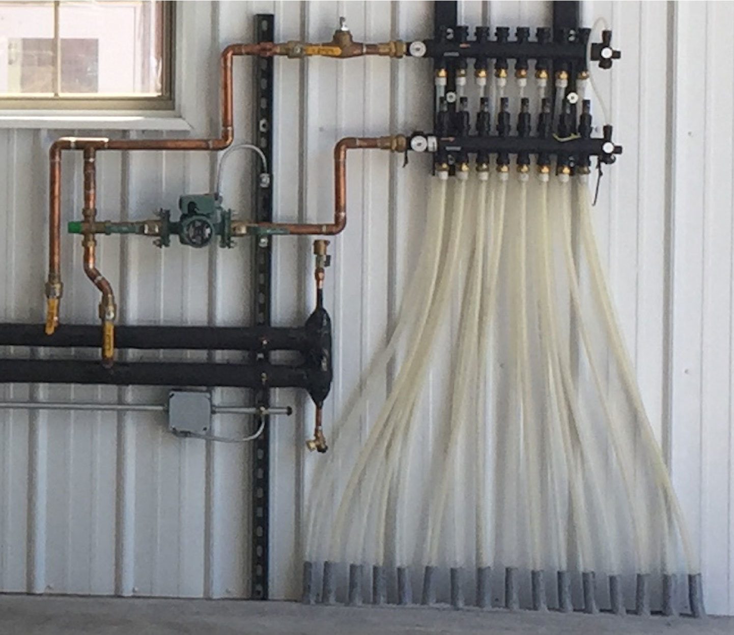
ENLARGE
FIGURE 1
Figure 2 is a schematic for what I believe to be the piping and hardware in this photo.
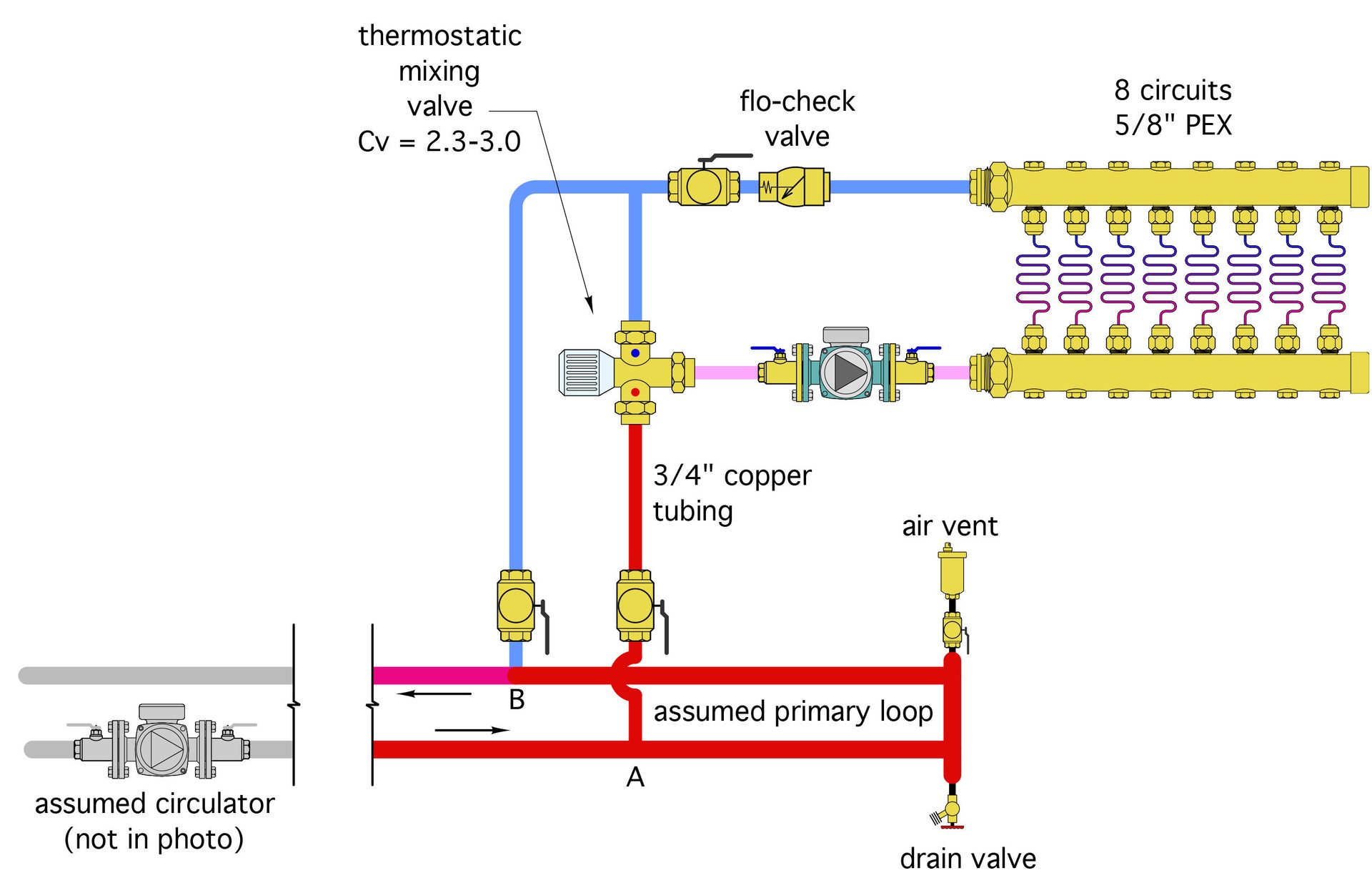
ENLARGE
FIGURE 2
Imagine that you, an independent heating pro, have been asked to inspect this system because the owner is claiming it doesn’t deliver sufficient heat on cold days. You’ve already checked out the boiler and near boiler piping, and determined that it was done correctly, and is not the source of the complaint.
Can you spot any potential issues with this portion of the installation? What would you propose to correct what you consider as deficiencies in this layout?
Are you an ace troubleshooter?
Within the pages of this magazine, PM’s Hydronics Editor John Siegenthaler, P.E., will pose a question to you, our readers, to review a system’s schematic layout and discover its faults, flaws and defects. Discover archived “The Glitch & The Fix” exercises at its radiant-focused website, www.radiantandhydronics.com. Good luck!