
HYDRONICS WORKSHOP
BY JOHN SIEGENTHALER
Toggle time
How mismatched loads in a dual-temperature heat pump system can limit performance.

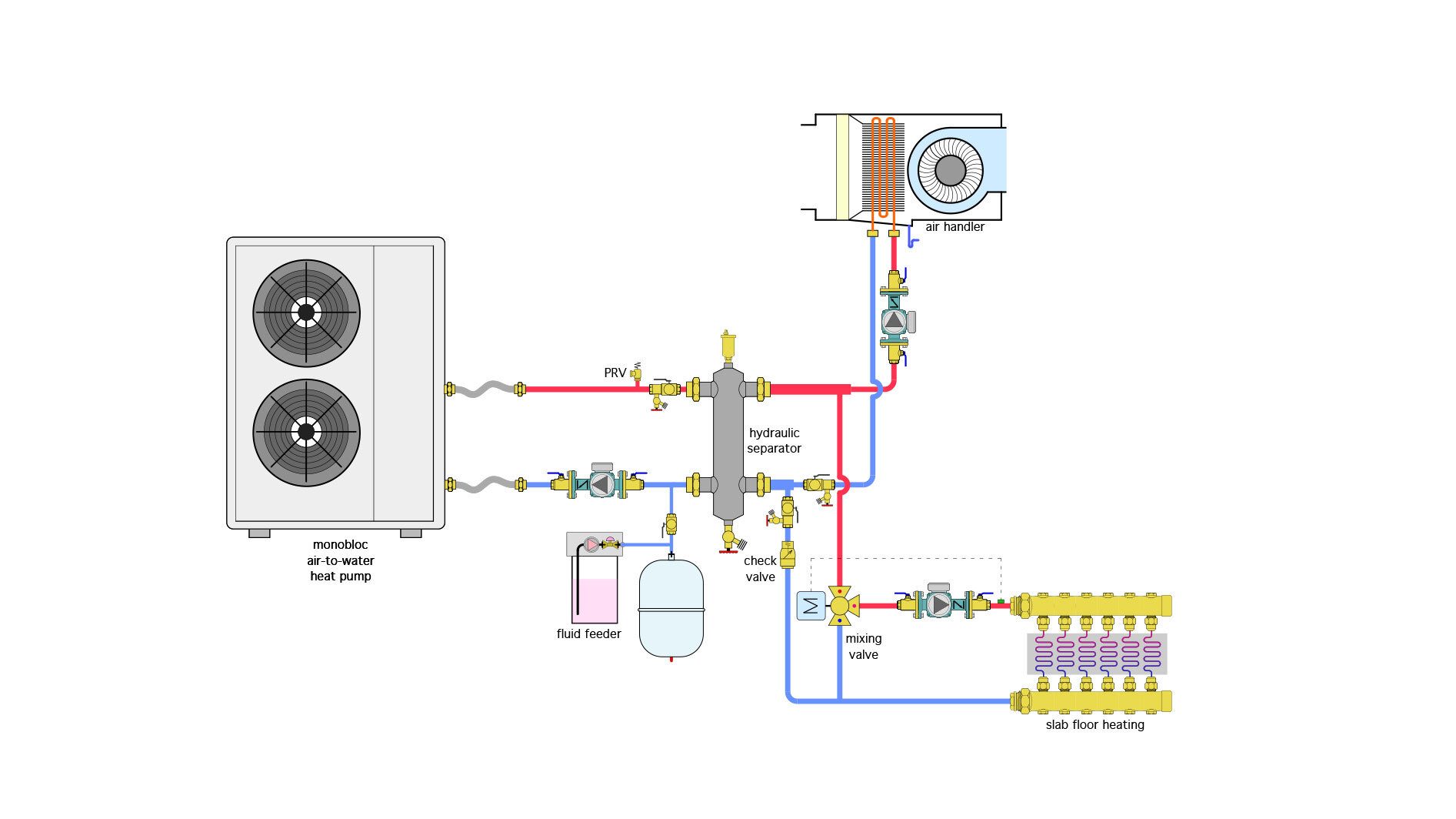
Consider the dual temperature heat pump system shown in figure 1.
ENLARGE
FIGURE 1
The air-to-water heat pump has a nominal 4-ton (48,000 Btu/hr) heat output rating. It supplies an air handler as well as a heated concrete slab.
At design load conditions the air handler is rated for 20,000 Btu/hr at a supply water temperature of 120 ºF. The slab is designed to release 20,000 Btu/hr when supplied with water at 105 ºF.
To produce these different supply water temperatures the installer decides to set up the heat pump controls for a supply temperature of 120 ºF, and use a motorized 3-way mixing valve to reduce the water temperature to the floor heating circuits.
When only the air handler is operating, the heat pump is able to supply the 120 ºF water. Whenever the heated slab is operating by itself, the heat pump has no problem providing the required water temperature. However, when the floor heating zone and the air handler are operating at the same time and the outdoor air temperature is around 24 ºF, the fluid temperature leaving the heat pump can’t climb above 103 ºF.
What’s wrong?
All hydronic systems seek to operate at “thermal equilibrium.” That’s a steady state condition where the rate of heat production by the heat source is the same as the rate of heat dissipation by the load.
The greater the heat emitter surface area available to dissipate heat, the lower the water temperature will be when thermal equilibrium is achieved.
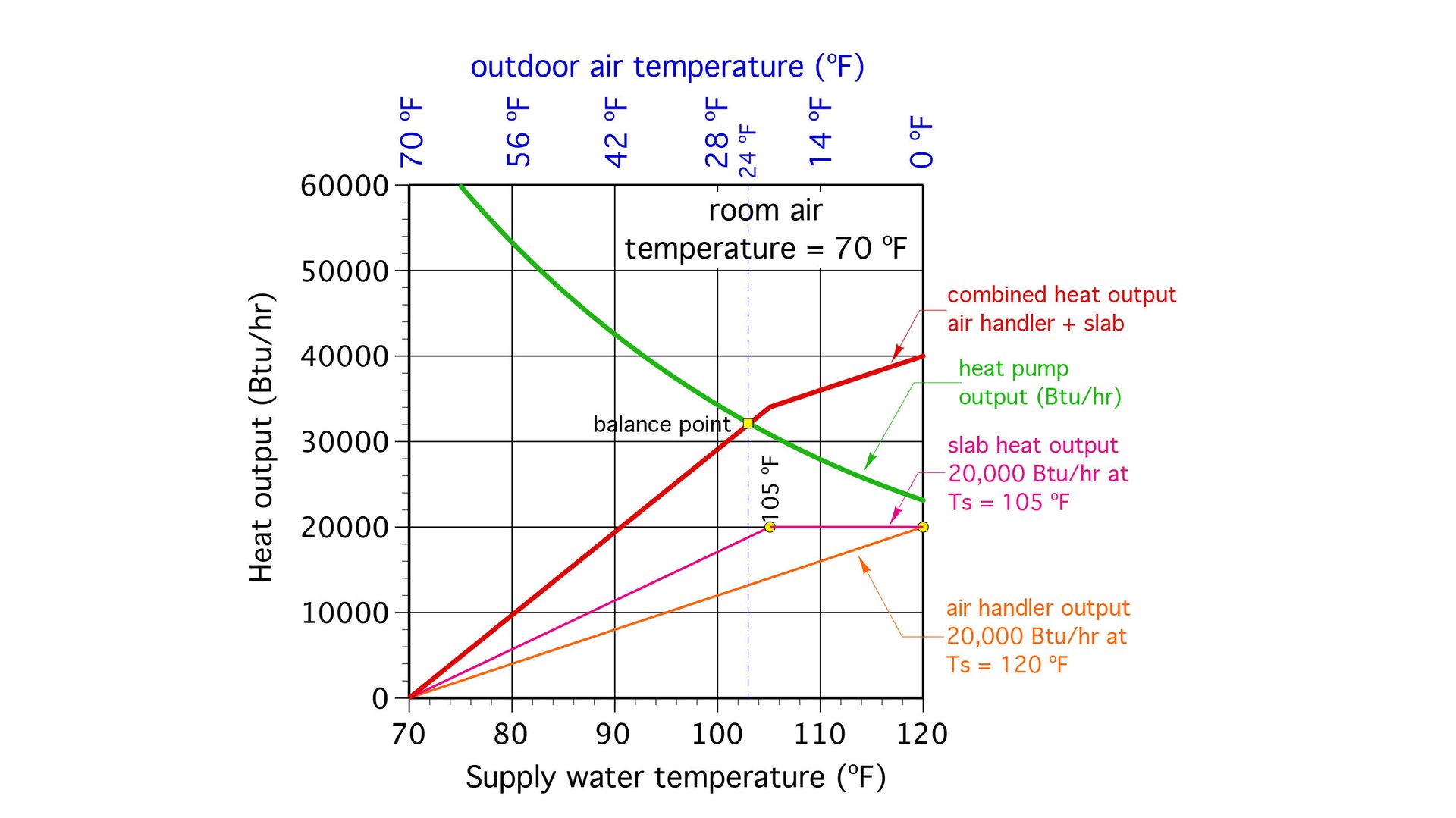
Figure 2 shows how the heat output of the floor slab and air handler vary based on supply water temperature. The room air temperature is assumed to be 70 ºF.
ENLARGE
FIGURE 2
At a supply water temperature of 103 ºF, the heating capacity of the heat pump is the same as the total heat dissipation ability of the distribution system. That’s where this system achieves thermal equilibrium. The floor heating zone is fine at this condition, but the output of the air handler is significantly lower than what was planned for based on the assumption that 120 ºF supply water would be available.
What to do?
One way to overcome this issue is to install a heat pump with a higher heating capacity. This would shift the balance point up and to the right, allowing for a higher supply water temperature to the air handler who both loads are operating at the same time. However, that higher supply temperature still might not make it up to 120 ºF under design load conditions.
Beyond this uncertainty is the daunting and very expensive change out of the existing heat pump for a higher capacity unit. Doing so could also lead to short cycling under partial load conditions, especially if the larger heat pump is a single speed unit.
Switch-a-roo
A more practical approach is to “share” the heat pump’s heat output between the two loads. I refer to this as “load toggling.” It requires detection of when both loads are calling for operation at the same time. When that occurs, the controls need to only allow one load to operate for a specific time and then switch to the other load, as the only load, for another specific time. For example, when both loads in figure 1 are calling for operation at the same time, slab heating might be allowed to operate for 25 minutes with the air handler off, followed by the air handler running for 35 minutes with the slab off.
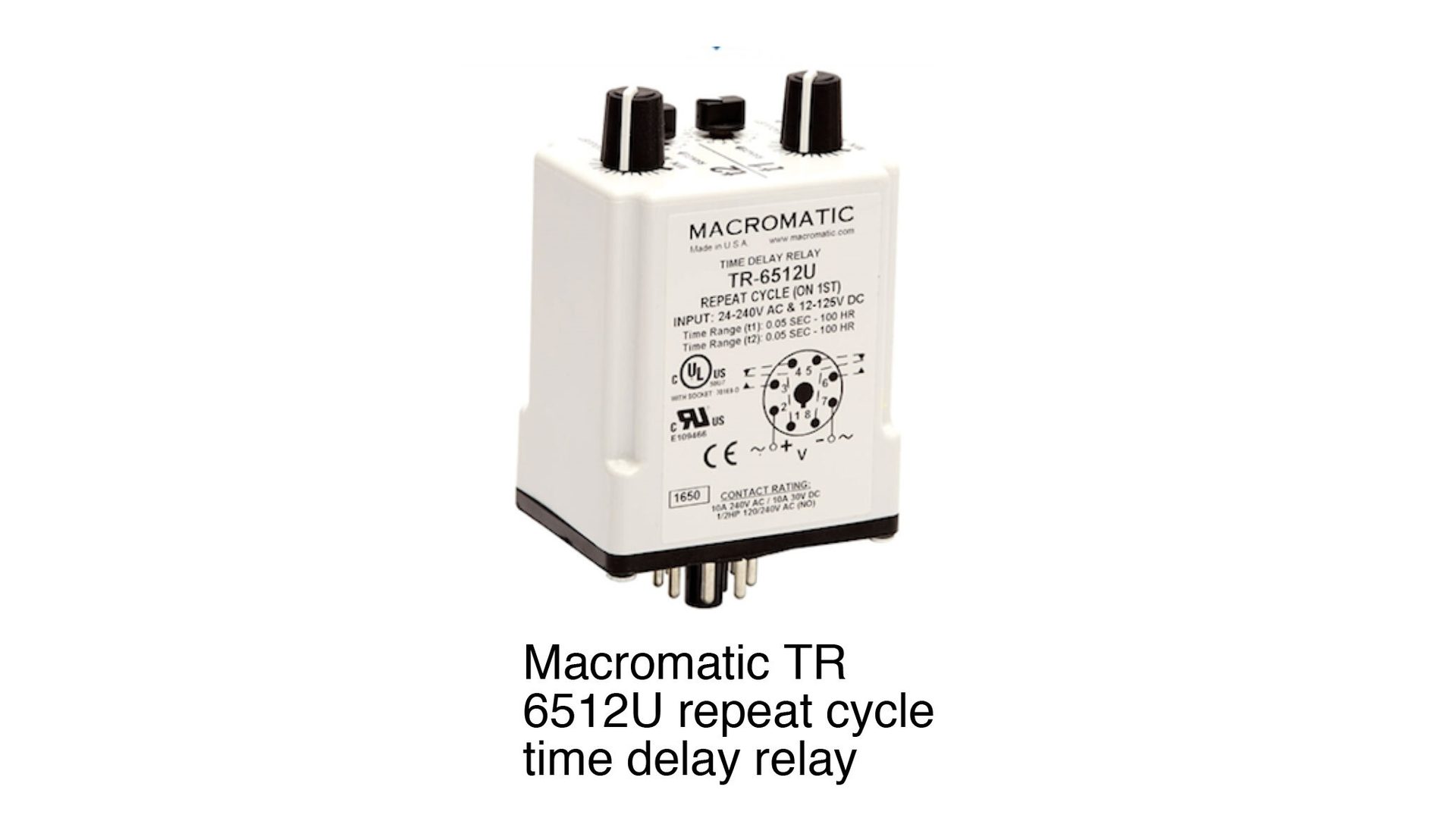
Load toggling can be accomplished using a repeat cycle time delay relay, such as the one shown in figure 3.
ENLARGE
FIGURE 3
This relay has multiple operating modes and settings for those modes. For the toggling application, the mode setting would be “flashing.” For the relay shown in figure 3, the time over which each cycle of the relay’s contacts occurs is adjustable from 0.05 seconds to over 100 hours. For this application, a time interval of several minutes is appropriate. For example, allowing the air handler to operate for 30 minutes with no heat input to the slab, and then switching it off and allowing slab heating to operate for the next 20 minutes with no heat input to the air handler. This 30/20-time interval then repeats as long as both loads are calling for heat.
For the relay in figure 3, these time intervals are easily adjusted. That relay has double pole/double throw (DPDT) contacts, and mounts into a standard 8-pin octal relay socket. It’s enabled to operate whenever 24 VAC is applied to the coil.
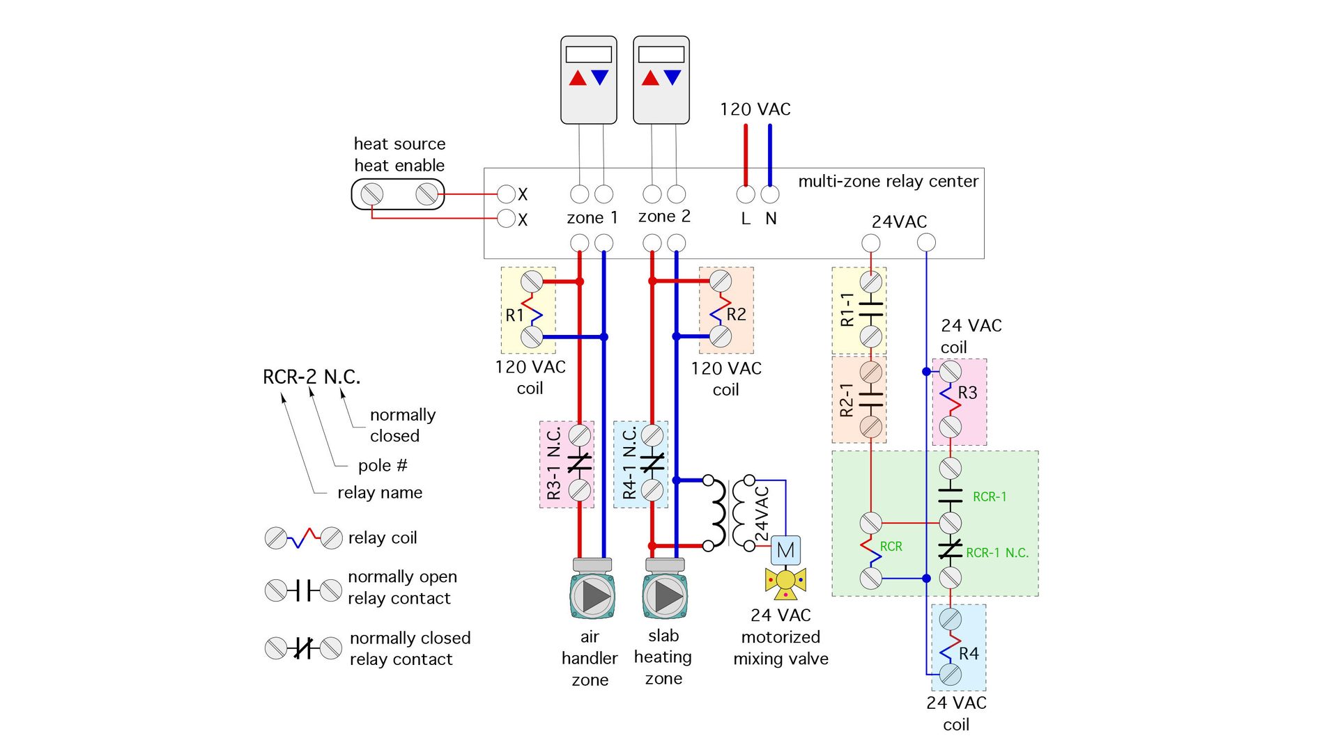
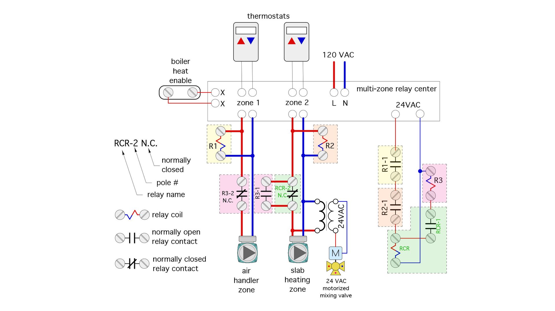
Figure 4 shows a wiring schematic where the repeat cycle time delay relay (RCR) is combined with 4 other single pole / double throw (SPDT) relays.
ENLARGE
FIGURE 4
Relays (R1) and (R2) have 120 VAC coils and are wired in parallel with their associated zone circulator. Their function is to “detect” when their associated zone circulator is called to operate by the multi-zone relay panel.
A normally open contact in relay (R1), designated as (R1-1), is wired in series with a normally open contact in relay (R2), designated as (R2-1). When both of these contacts are closed, 24VAC from the zone relay panel or a separate 24VAC transformer passes to the coil of the repeat cycle time delay relay (RCR), and it begins its first timing cycle.
The (RCR) relay has been configured so that the first timing cycle immediately sets the following contact status:
- RCR-1 closes
- R3 coil is energized
- R3-1 N.C. opens (turning off the air handler circulator)
- RCR-1 N.C. opens
- R4 coil is off
- R4-1 N.C. remains closed (allowing the slab circulator to run)
At the end of the first timing cycle, the status of the relay contacts change to the following:
- RCR-1 opens
- R3 coil is off
- R3-1 N.C. closes (allowing the air handler circulator to run)
- RCR-1 N.C. closes
- R4 coil is energized
- R4-1 N.C. opens (turning off the slab circulator)
At the end of the second time period, the above “toggling” actions repeat as long as both loads are still calling for heat. When only one load is operating the repeat cycle time delay relay (RCR) is not energized, and relay contacts R3-1 N.C. and R4-1 N.C. are both closed. The active load is controlled solely by its associated thermostat.
Easy to acquire: Relays (R1), (R2), (R3), and (R4) are simple single pole double throw (SPDT) relays. (R1) and (R2) must have 120 VAC rated coils, while (R3) and (R4) must have 24 VAC rated coils with 24 VAC coils. The contacts in relays (R1) and (R2) are only handling a fraction of one amp in low voltage circuits. The contacts in relays (R3) and (R4) handle the current needed to operate one of the circulators. Most residential and light commercial zone pumps only require 1 to 2 amps.
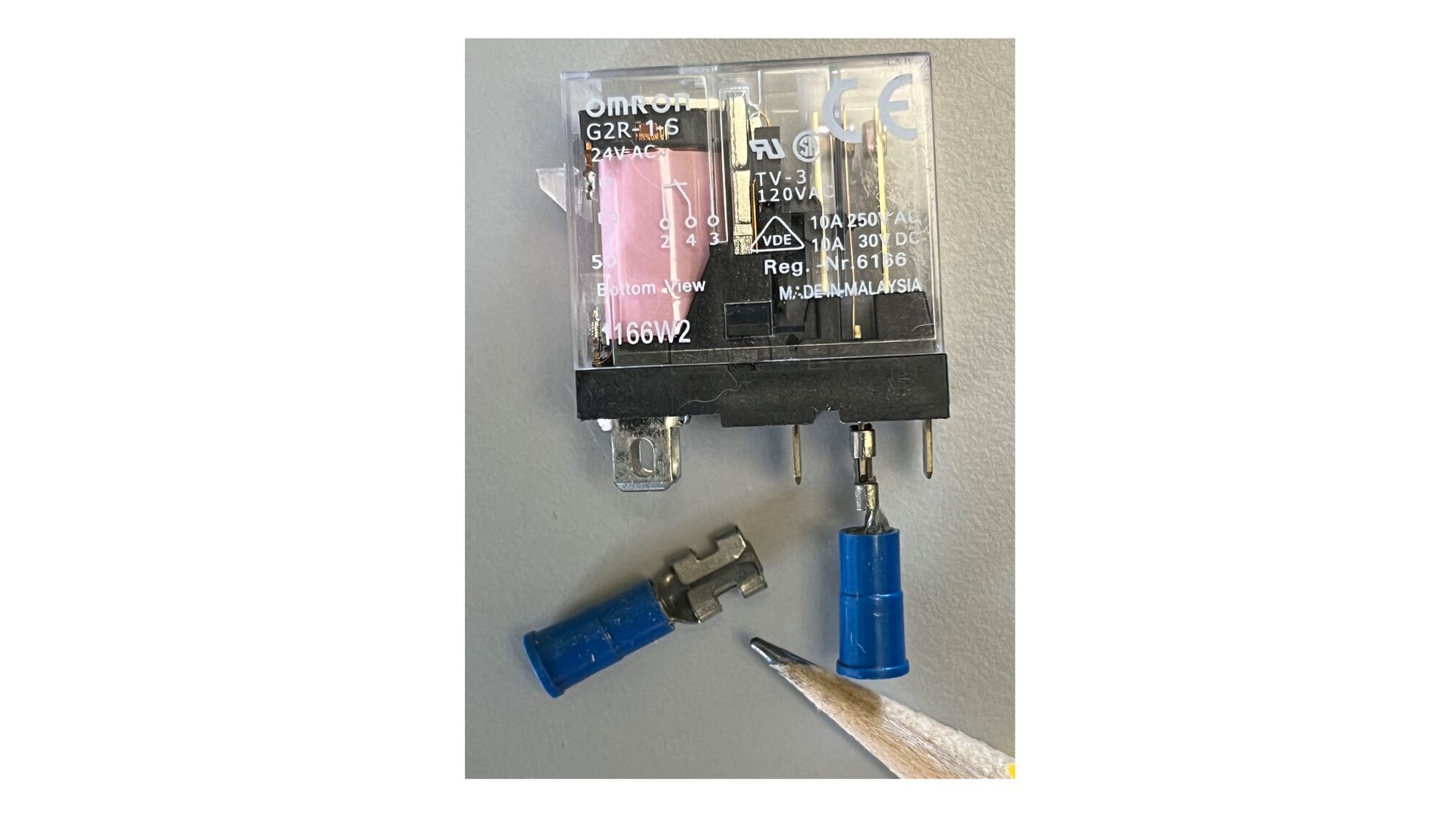
Figure 5 shows a product that can be used for relays (R3) and (R4). It’s an OMRON G2S-1-S, with 24VAC coil and contacts rated up to 10 amps. A very similar relay, OMRON G2S-1-T, has a 120 VAC coil, and can be used for relays (R1) and (R2).
ENLARGE
FIGURE 5
You can buy these relays online in the price range of $4 to $9 each depending on quantity. They can be mounted on relay sockets or directly wired using quick connect terminals as shown in figure 4.
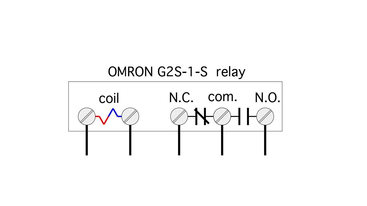
These relays have clear plastic cases through which you can see the contacts. The two contacts that are touching each other are the normally-closed contacts. The two contacts with a gap between them are the normally-open contacts. The two connections for the coil are grouped together. The three connections for the contacts are also grouped together, as shown in figure 6.
ENLARGE
FIGURE 6
These relays can be mounted in any orientation. Be sure to use an indelible marker to label each relay. Also, be sure to leave a wiring diagram such as the one in figure 3 with the system documentation so that any future technician can see how the coils and contacts need to be arranged.
It’s worth mentioning that the same operating logic could be done using 3 relays rather than the 4 (SPDT) relays shown in figure 3. However, one of those relays has to be at least a double pole double throw (DPDT) relay. They’re available, but are considerably more expensive than the OMRON (SPDT) relays mentioned earlier. Figure 7 shows the required wiring.
ENLARGE
FIGURE 7
Final thoughts
If you apply this technique, be sure that the zones in the multi-zone relay center are not configured for priority operation. Relays other than those mentioned above – but with equivalent functionality – could be used. Be sure that the coil voltages for the relays are correct, and that the current rating of the relays is suitable to handle the current required by the circulators.
At a supply water temperature of 103 ºF, the heating capacity of the heat pump is the same as the total heat dissipation ability of the distribution system. That’s where this system achieves thermal equilibrium.
I suggest wiring the relays as shown in the schematics and testing the operation of the overall control system prior to installing it on-site.
Load toggling is well applied in systems where one of the loads is a high thermal mass heat emitter, such as a heated floor slab. The thermal mass of a heated slab tends to dampen out “pulsed” heat inputs with virtually no noticeable effects on comfort.
Pulsed heat input to low thermal mass heat emitters, such as the air handler, will be more noticeable. Still, as long as those low mass emitters can deliver the total heating energy needed by the space averaged over a period of perhaps an hour, the average interior temperature should not vary more than it would with any low mass emitter operated by a thermostat.

Lead image courtesy of Douglas Rissing / iStock / Getty Images Plus
John Siegenthaler, P.E., is a consulting engineer and principal of Appropriate Designs in Holland Patent, New York. In partnership with HeatSpring, he has developed several online courses that provide in-depth, design-level training in modern hydronics systems, air-to-water heat pumps and biomass boiler systems. Additional information and resources for hydronic system design are available on Siegenthaler’s website, www.hydronicpros.com. Contact him at hydronicpros@gmail.com.