
HYDRONICS WORKSHOP
BY JOHN SIEGENTHALER
Air-to-slab
Combining an air-to-water heat pump with a heated floor slab.

Over the last few years, I’ve written several columns describing how air-to-water heat pumps can provide heating, cooling and domestic hot water for homes. Many of the systems involve buffer tanks to help stabilize heat transfer from the heat pump to a zoned distribution system. Those tanks are especially important with a single-speed heat pump supplying a highly zoned distribution system. Without the thermal mass they provide, the single-speed heat pump would undergo frequent on/off cycling that ultimately leads to premature failure of components, such as compressor contactors or start capacitors. Short cycling also lowers the overall efficiency of the heat pump.
The emergence of air-to-water heat pumps with inverter-driven variable speed heat pumps allows heat output to be reduced down to about 30% of the heat pump’s rated capacity. This can reduce the size of the buffer tank — perhaps into the range of 25 to 40 gallons in typical residential systems, depending on the extent of independent zoning.
This month I want to look at potential applications for air-to-water heat pumps that could eliminate the need for a buffer tank.
Massive advantages
Consider all the non-residential buildings that could be served by a single zone heated floor slab. Examples include highway garages, farm shops, automobile service facilities, small aircraft hangers or RV showrooms. Workshops used for woodworking or metal fabrication often have similar heating needs. So do light manufacturing or assembly facilities with open floor plans. Warehouse areas where materials are stored on racks (rather than directly on floors) would also fall into a similar category.
The common thread here is a heated floor slab that adds lots of thermal mass to the system, combined with minimal zoning, which keeps most if not all of that thermal mass “online” whenever the system is operating.
Here’s an example, a farm shop building has a 40 foot by 80 foot footprint. Due to the heavy equipment it’s designed to handle, the concrete slab is 6 inches thick, and rests on 2 inches of extruded polystyrene. The thermal mass of that slab is its volume multiplied by the heat capacity of concrete:
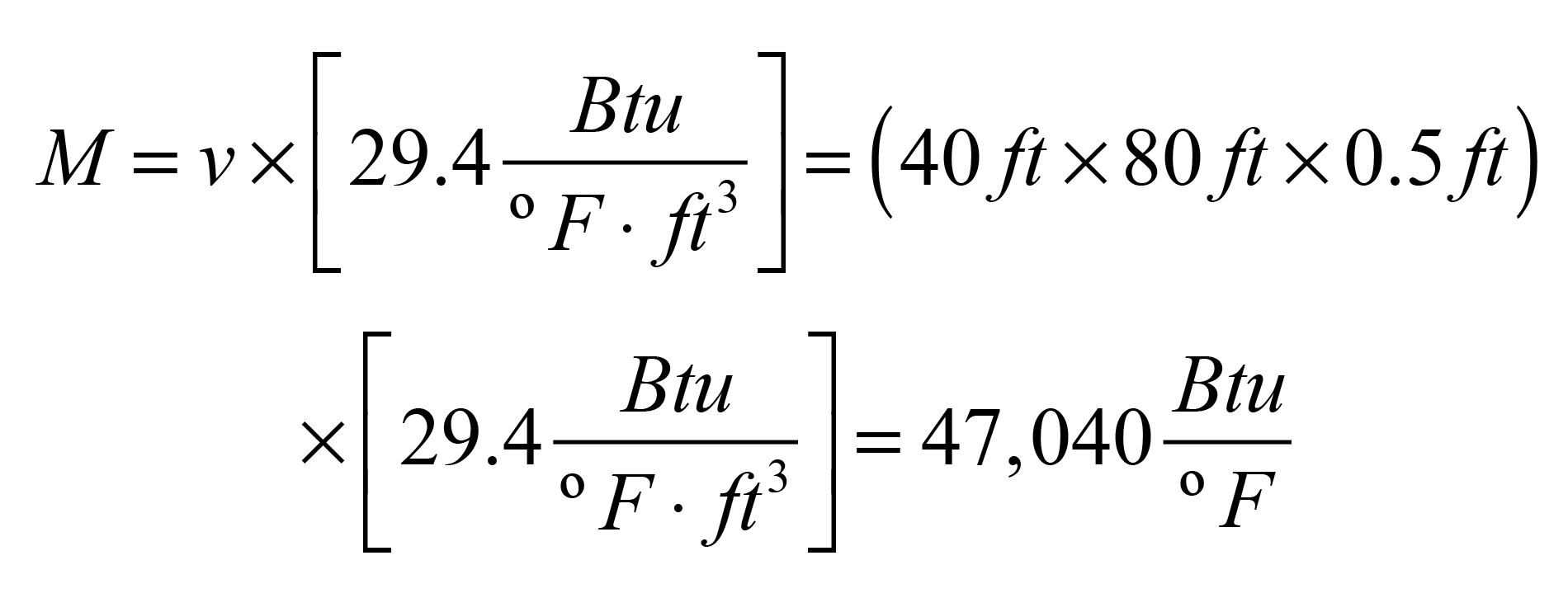
That’s the equivalent to 5,646 gallons of water storage. Imagine a buffer tank of that volume. All that thermal storage is already in the system, as concrete rather than water.
The best way to keep that mass “online” is constant circulation through the floor circuits. Doing so also helps even out slab temperatures because it moves heat stored in the core area of the slab to the cooler areas near perimeters and just inside overhead doors.
Simplest systems
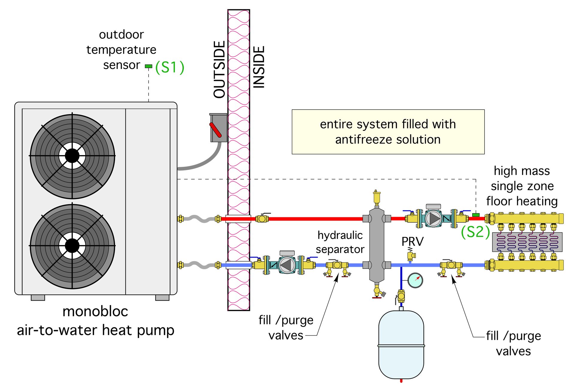
The system layout shown in Figure 1 is about as simple as it gets.
ENLARGE
FIGURE 1
A hydraulic separator connects the heat pump circuit to a manifold station supplying the floor heating circuits. Constant circulation is maintained between the hydraulic separator and the floor circuits. The heat pump and its associated circulator are turned on and off based on the supply water temperature to the manifold station.
The preferred method for determining the required “target” supply water temperature at sensor (S2) is outdoor reset control. An inexpensive controller (or perhaps the controller built in the heat pump) continually calculates the target supply water temperature based on current outdoor temperature. When the measured supply water temperature drops 3° or 4° F below the target temperature, the heat pump and its circulator are turned on. They continue to run until the measured supply water temperature is 3° to 4° F above the target value. The on/off differential of 6° to 8° F, should allow for relatively long heat pump on-times and off-times while still keeping the average water temperature relatively close to the target value. The heat pump on/off cycle times can be lengthened by widening the on/off differential setting of the reset controller. However, wider differential settings also increase the chances of “feeling” differences in comfort. A little experimentation with the differential settings will find the “happy spot” for each individual building and its hydronic distribution system.
Air-to-water heat pumps equipped with variable speed compressors are likely to have built-in outdoor reset capability. The compressor modulates its speed in an attempt to hold a specific outlet water temperature. The temperature is most likely measured by a factory-installed sensor near the outlet of the heat pump. This is not ideal when the heat pump is coupled to the distribution system using any type of hydraulic separation technique. The potential problem is differences in flow rates between the heat pump circuit and the distribution circuit. Any difference in these two flow rates sets up mixing inside the hydraulic separator. When the load side flow rate is higher than the heat pump side flow rate, the water temperature supplied to the manifold will be less than the temperature leaving the heat pump. These two temperatures will only be the same when the two flow rates are the same.
The best solution, assuming that the outdoor reset control action is being done by the heat pump’s internal controller, is the ability for the heat pump to monitor an external temperature sensor that’s mounted downstream of the hydraulic separation point. Sensor (S2) in Figure 1 is an example. That sensor measures the true supply temperature to manifold, after any mixing has taken place in the hydraulic separator.
Line them up
Current generation air-to-water heat pumps designed to operate on single phase 240 VAC power are limited to about 5 tons (60,000 Btu/h) rated heating capacity. When the design load of the building increases beyond the output of such a heat pump, a couple of options are possible.
One is to look at higher capacity 3-phase air-to-water heat pumps. They’re available in several heating capacity ranges, some of which top out at over 200 tons. Their use is obviously dependent on the availability of 3-phase power and sufficient service entrance capacity.
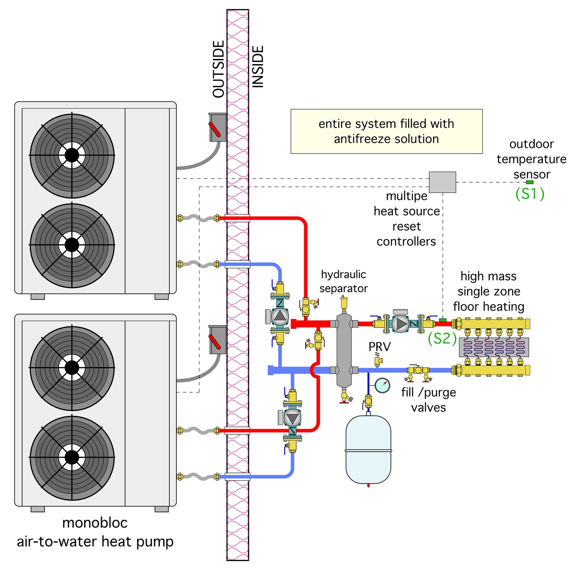
The other option is to use two or more single-phase heat pumps in a staged arrangement as shown in Figure 2.
ENLARGE
FIGURE 2
Some of the newest air-to-water heat pumps may have internal firmware allowing them to coordinate multiple heat pumps. If not, there are several off-the-shelf multiple boiler controllers that could be used.
As is the case with multiple boiler systems, multiple heat pumps provide better load matching and partial capacity if one heat pump is down for serving.
Added functionality
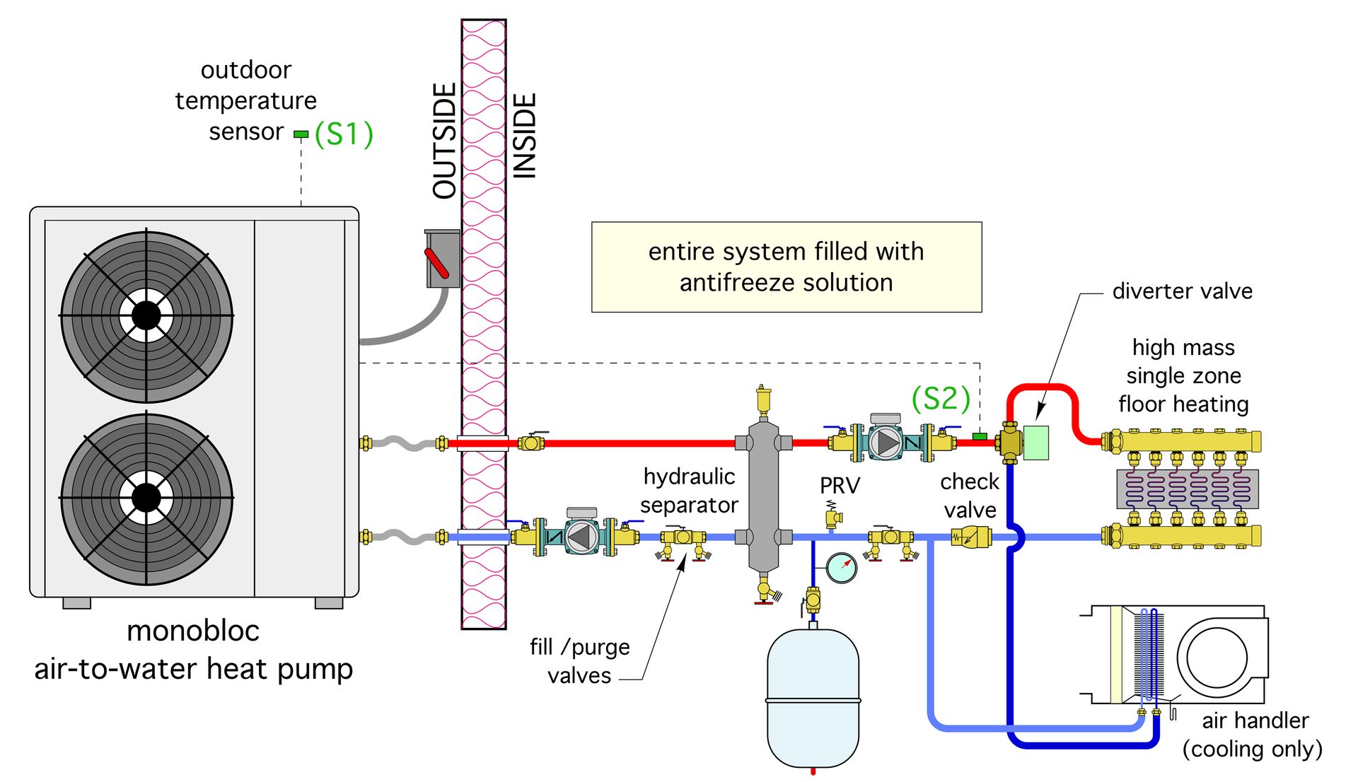
Although the primary application we’re focusing on is floor heating, these heat pumps have reversing valves that allow them to supply chilled water cooling. That’s a very sellable upgrade in many of these buildings where equipment, lighting, tools and people all generate heat. It’s also relatively easy to accomplish using one or more chilled water air handlers. Figure 3 shows one approach.
ENLARGE
FIGURE 3
A motorized diverter valve is shown downstream of the hydraulic separator. It routes the output stream from the heat pump to the floor slab during heating mode, or the chilled water air handler in cooling mode. It’s also possible to use a manually operated 3-way diverter valve rather than the motorized diverter valve. That would reduce cost, but don’t forget to change the valve setting whenever switching between heating and cooling mode.
The system in Figure 3 also assumes that the same circulator that supplies the floor heating system has the flow and head capacity to supply the chilled water subsystem. Be sure to verify this during design. If there are significant differences in the flow and head requirements, it’s better to use two circulators, each sized for its specific subsystem. Doing so also eliminates the need for a diverter valve, but be sure to include check valves in each subsystem.
The air handler has much less thermal mass than the heated floor slab. Since there’s no buffer tank in the system, it’s critically important to match the cooling capacity of the air handler with the cooling capacity of the heat pump. Match these capacities for chilled water temperatures in the range of 45° to 55° F.
If the heat pump has a variable speed compressor, it should be able to adjust speed as necessary to hold a target chilled water outlet temperature. This allows the cooling capacity of the air handler to be lower than the rated cooling capacity of the heat pump. However, make sure that the air handler’s cooling capacity is not less than the cooling capacity of the heat pump when it’s operating at minimum compressor speed.
Finally, if you’re going to be doing cooling, be sure that all the piping and components that convey chilled water are insulated and vapor sealed.
Domestic water heating is also a possibility, but before going in that direction be sure that the load justifies the added cost and complexity. In many garage or shop-type buildings, the DHW load might only be one or two sinks. No showers, kitchen, washing machine or other significant needs for hot water are present. These light loads can be handled by small electric tankless water heaters. The small amount of electric energy they require doesn’t justify the use of an indirect tank or controls that switch the heat pump between space conditioning and DHW loads.
Garage and shop buildings may not have the “glamour” of custom residential design, but their suitability for conditioning using an air-to-water heat pump combined with slab heating is nonetheless compelling. The system design is simple, especially in comparison to what some custom residential projects might require. Keep these simple approaches in mind as electrification efforts for all types of buildings continue to present new opportunities.

Figures courtesy of John Siegenthaler. Hero image: breifbluesky / iStock / Getty Images Plus via Getty Images.
John Siegenthaler, P.E., is a consulting engineer and principal of Appropriate Designs in Holland Patent, New York. In partnership with HeatSpring, he has developed several online courses that provide in-depth, design-level training in modern hydronics systems, air-to-water heat pumps and biomass boiler systems. The fourth edition of his textbook — “Modern Hydronic Heating & Cooling” — was released in April. For more information, visit, www.hydronicpros.com.