Strung out
The Glitch:
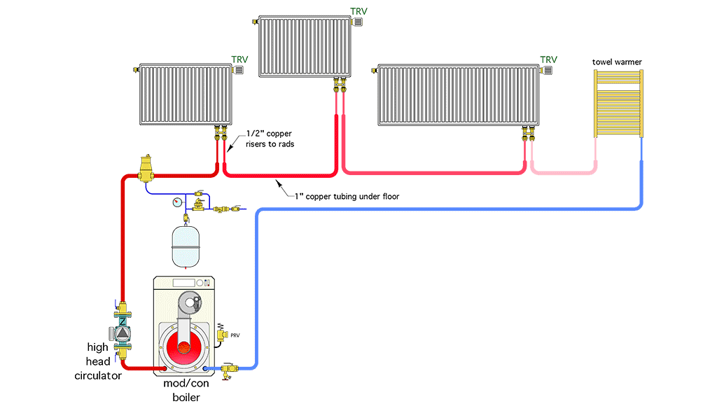
An installer is asked to create a small heating system using three panel radiators and a towel warmer. The design load for all the heat emitters is 25,000 Btu/h. To keep things simple, the installer connects all the emitters as shown in Figure 1. Each panel radiator has a dual isolation valve — 1/2-inch copper risers connect to this valve and run down through the floor, where they connect to 1-inch copper piping. The installer opted to use 1-inch copper tubing under the floor to keep the head loss of the circuit down. Because the system uses a 50,000 Btu/h mod/con boiler with a compact heat exchanger, the installer selected a high head circulator as “insurance” that a high flow rate would be established in the circuit to reduce the overall temperature drop. A thermostatic radiator valve was installed on each of the panel radiators to prevent any of the rooms in which the radiators were located from overheating. Can you spot several problems with this layout and come up with an alternative that resolves these issues?
ENLARGE
Are you an ace troubleshooter?
Within the pages of this magazine, PM’s Hydronics Editor John Siegenthaler, P.E., will pose a question to you, our readers, to review a system’s schematic layout and discover its faults, flaws and defects. Discover archived “The Glitch & The Fix” exercises at its radiant-focused website, www.radiantandhydronics.com. Good luck!