Kazi Nasir
VRF versus
HYDRONICS
Comparing HVAC technologies and associated costs.
The Hydronics Industry Alliance released a report studying a VRF system and hydronic system installed in the same building. The report found the VRF system had higher energy consumption in three consecutive years of operation.
With a considerable volume of contradictory information in circulation regarding the application of different technologies for HVAC systems, this article seeks to explain some of the technical aspects of variable refrigerant flow (VRF) systems, and offer comparisons on the basis of cost and performance to more standard hydronic systems. While some of the material presented here are drawn from industry literature, the majority is drawn from peer-reviewed studies conducted by recognized industry professionals.
What is a VRF system?
Variable refrigerant flow (VRF), also known as variable refrigerant volume, is a system that uses refrigerant, most commonly R-410A, as the working fluid to distribute heat within a building. System output is regulated based on system load, where the refrigerant flow is regulated by electronic expansion valves and variable speed compressors.
VRF is a relatively new technology, first developed in Japan in the 1980s. VRF system designs first appeared on the North American market in the early 2000s.
In general, VRF systems consist of a central outdoor unit with integrated variable speed compressor(s) and multiple indoor units of different types and capacities, modulated by electronic expansion valves (EEVs). VRF system designs typically arrange system controls in a daisy-chain configuration, and typically use a single piping system connected in both series and parallel.
How does a VRF system work?
At a high level, the sequence of operation for a VRF system is as follows:
- Local controllers compare setpoints with room temperatures and direct corresponding expansion valves to open or close as a way to modulate flow within the system;
- A central controller consolidates data from all controllers to understand the net load, and adjusts compressor speed to not only match the thermodynamic properties of the refrigerant to the required load, but also add the pressure required for the movement of refrigerant to provide adequate distribution of heat; and
- When operating in a cooling mode, expansion valves reduce the pressure of the refrigerant as it enters the evaporators. The refrigerant absorbs energy from the conditioned space and transports it back to the compressor. The condenser rejects heat gathered by the refrigerant to the exterior of the building.
Limitations to consider
Proponents indicate that VRF systems offer benefits in the consistency of comfort, energy efficiency, zoned heating and cooling, the ability to heat and cool simultaneously and installation flexibility, particularly for tight spaces. For select installations or building types, those arguments may be valid. However, there are some important limitations that the VRF technology imposes on buildings and HVAC systems, starting as early as the design stages.
For select installations or building types those arguments about the benefits of VRF systems may be valid. However, there are some important limitations that VRF technology imposes on buildings and HVAC systems, starting as early as the design stages.
Addressing HVAC loads — maximum system capacity, effects of outdoor air temperature and piping design
VRF technology places noteworthy limitations on the total length of pipe within a system. Rated capacity decreases as the piping length increases, but this actually starts at quite a short length. Because ASHRAE standards rate a VRF system based on 25 feet of piping and zero vertical separation between indoor and outdoor units, rated capacity of VRF systems start to decrease when pipe length and vertical separation goes beyond 25 feet and 0 feet, respectively.
Capacity decreases continue as system sizes expand. Where the total piping length is 600 feet, systems have lost 10% of total capacity. And where designers might choose systems for larger buildings, VRF cannot function beyond the maximum piping length of 3,281 feet. At that stage, more than 50% capacity has been lost.
VRF technology also has limitations on the capacity of the system to effectively heat or cool conditioned space to meet indoor air temperature requirements. Maximum capacity available for cooling has been shown to be to be ~44tons (528MBH), and maximum capacity for heating is ~49.5tons (594MBH). Where greater heating and cooling capacities are required, designs must accommodate a separate system, with independent piping and independent networks of controls.
In addition, the effectiveness and efficiencies of VRF systems decline as outdoor air temperatures (OAT) decrease. Heating capacity available at an OAT of 5° F is at best 70% of the heating capacity available at 60° OAT. And, design considerations must be made to address a 50% decrease in heating capacity at 0°, compared to rated conditions. In many installations, supplemental heat sources are required, which will have a direct impact on the total energy consumed by an HVAC system, just to maintain design conditions.
Occupant health and safety
While instances of refrigerant leakage are few, the risks posed by VRF systems are nonetheless concerning. R-410A is a colorless, odorless gas that has the potential to induce asphyxiation. Because the design of VRF systems rely on refrigerant as the working fluid and system piping (filled with R-410A) has to be installed across the entire envelope of the building, VRF systems have hundreds (if not thousands) of feet of piping, filled with hundreds of kilograms of pressurized refrigerant.
Unfortunately, the very nature of how VRF operates (modulating refrigerant pressure) is also why VRF systems lack leak detection systems. Compounded by the fact that long piping networks create difficulty in locating refrigerant leaks, which leads to higher concerns for occupant health and safety. For this reason, ASHRAE 15 put forward design requirements that limit the total refrigerant volume contained within a system based on the volume of the smallest space served by the system.
Unfortunately, these safety requirements are often inadequately addressed using door diffusers and/or common ceiling plenums. Properly addressing the risk of R-410A leakage requires extensive design considerations and added costs such as refrigerant detectors, separate systems for smaller spaces, piping re-arrangement, etc.
VRF systems must be installed using copper piping whereas hydronic piping offers many options.
Cost considerations — installation
Where VRF system designs have unique strengths and benefits for buildings and spaces of particular sizes, many of the industry claims of cost savings relative to other industry standard system designs are based on antiquated comparisons that do not hold up to careful review.
In an article published in Plumbing & Mechanical in 2013, Greg Cunniff notes that cost differences for installation are primarily the result of the requirement for more complicated refrigerant management systems and controls in VRF systems. Key differences hinge on factors such as:
- Design changes required to safely accommodate refrigerant as a working fluid;
- More stringent installation requirements; and
- Differences in piping and piping installation costs.
A 2004 review of costs showed that initial estimates of installed cost premiums for VRF systems range from 5% to 20% more than conventional systems for a U.S. office building. In another more detailed study from 2013 called “Comparative Analysis of the VRF System and Conventional HVAC Systems, Focused on Life-Cycle Cost,” Jaesuk Park shows that VRF systems cost between $14.90/ft² and $34/ft² for schools and apartment buildings, respectively. Comparatively, traditional hydronic systems range from $11.90/ft² to $31/ft² for the same installation types (Park, 2013).
The cause for some of the cost differential comes from the added requirements on labor. Each installation step of VRF systems requires extra care and attention, and the techniques used extensively in hydronic system (to reduce installation cost and time) installations cannot be used in VRF systems.
In another Plumbing & Mechanical article published in 2017, Kyle DelPiano wrote “installers must be qualified to work with refrigerants under extremely high pressure and be knowledgeable about refrigerant piping locations under their state’s International Mechanical Code (IMC), as well as leak detection and ventilation requirements per ASHRAE Standard 15.”
In a 2015 article, “Modern Hydronics vs Variable Refrigerant Flow Systems,” John Siegenthaler showed that the larger proportion of the cost differential comes from differences in material requirements. VRF systems must be installed using copper piping whereas hydronic piping offers many options. As well, because of the high fluid pressures and temperatures of refrigerant in VRF systems, the grade of copper to be used must meet ASTM B280 standards and be suitable for operating pressure of 551 psig (LG). Industry cost data from 2020 shows that ASTM B280 rated copper costs $346.12 for 50 feet of 7/8-inch tubing whereas 60 feet of 2 1/2-inch Schedule 40 carbon steel piping (typical used for hydronic heating applications) cost only $22.80. As these numbers suggest, any claimed cost benefit resulting from VRF piping being smaller (diameter) than hydronic piping (for an equivalent load) is outweighed by the additional cost of material type and pressure rating.
Cost considerations — operation and maintenance
Manufacturers claim that the lifetime cost of VRF technology is lower than that of hydronics-based systems, stating that VRF wastes less energy, has higher rated efficiency and requires simpler, more streamlined maintenance. However, these industry claims are not supported by studies. Reviewing actual installed systems, a recent study by the Hydronic Industry Alliance looked at a VRF system and hydronic system, installed in the same building, addressing similar loads found that “On an annualized basis, the VRF system had an energy consumption 57% higher in 2010 than the hydronic system, 84% higher in 2011 and 61% higher in 2012.”
Not surprisingly, the increases in operating costs can be traced to the differences in system design, particularly in the handling of fluid. In a VRF system, the compressor serves double duty. It compresses and raises the temperature of the fluid and also serves as the pump to push the fluid around the building. An article published by the Hydronic Industry Alliance explains that, compared to hydronic systems, VRF systems employ much higher fluid velocities. These higher fluid velocities lead to greater pressure drops and higher compressor speeds, all of which causes increased energy consumption.
Studies have shown that of the overall energy usage, in VRF systems, a larger proportion of the total is expended on transport of the fluids. In his article, Cuniff estimates that where hydronic systems typically use 20% of total energy to move water, a VRF system uses as much as 30% on transport energy.
Where the many different types of HVAC systems and technologies offer unique benefits and to varying degrees cost advantages, it’s important to “look under the hood” to understand the technologies involved and make decisions for buildings and HVAC systems based on a foundation of facts and carefully administered studies. VRF systems undoubtedly have their place for select building sizes and types. However, for many standard building sizes and configurations, hydronic systems offer similar levels of occupant comfort at a substantially lower cost.

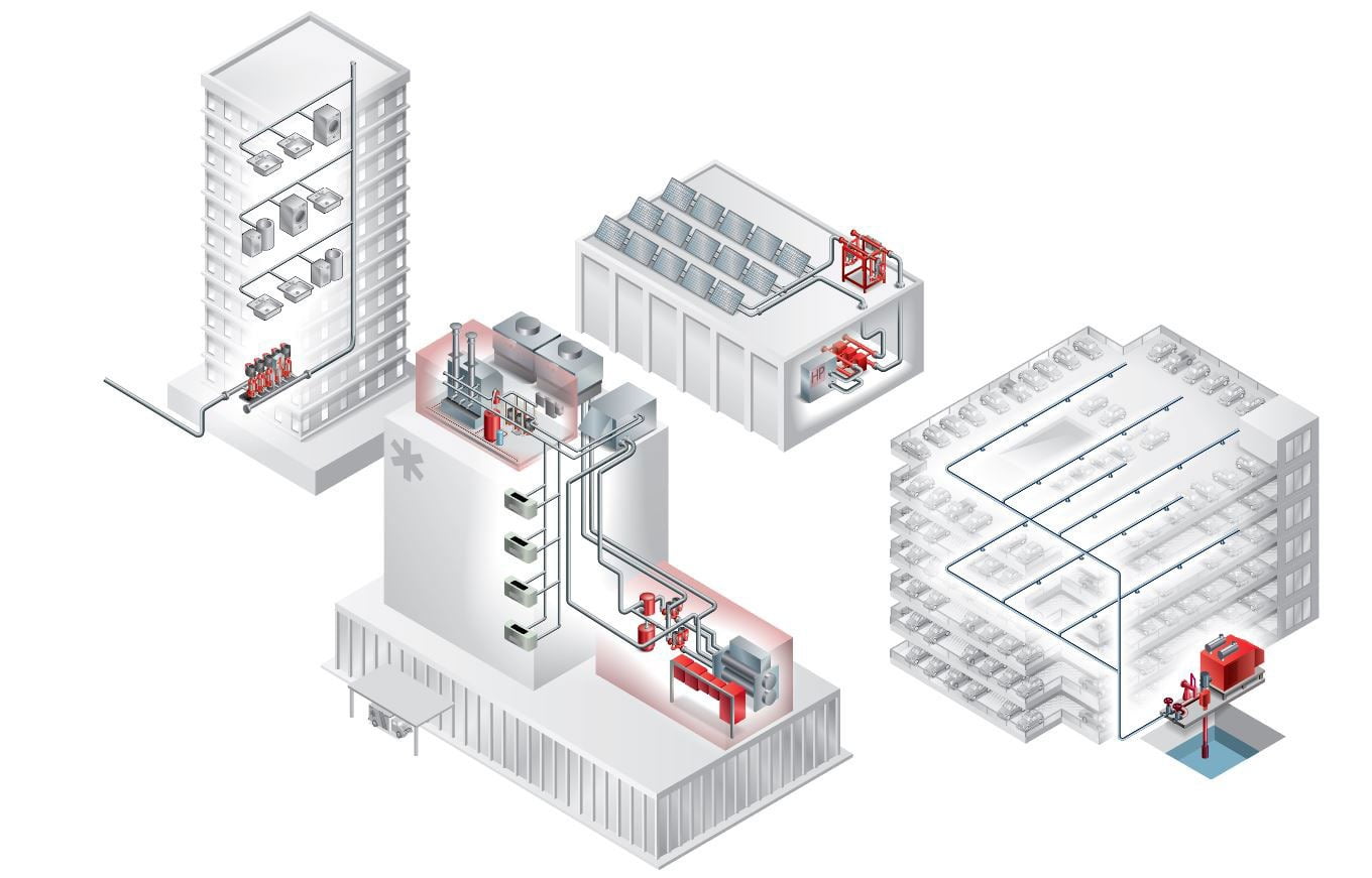
Hero and facility diagram courtesy of Armstrong Fluid Technology. Stock: alekseystemmer/iStock / Getty Images Plus via Getty Images
Kazi Nasir is global product experience specialist, plumbing and heat transfer for Armstrong Fluid Technology.