
HYDRONICS WORKSHOP
BY JOHN SIEGENTHALER
Keeping your cool
Important details for small-scale chilled water cooling.
Most of the modern hydronics technology used in North America for residential and light commercial buildings is for heating. Hydronic heat sources ranging from boilers to heat pumps to solar thermal collectors can be combined with many types of distribution systems and heat emitters. This allows systems to be configured for very specific comfort needs along with aesthetic preferences, budgets and fuel choices.
For decades, those interested in the versatility and superior comfort of hydronic heating have had to make decisions for cooling. Should it just be omitted? Should I install a separate forced-air cooling system? Is there a way to provide cooling using a hydronic system?
Those who’ve dealt with the HVAC systems in larger commercial or industrial buildings know that the answer to that last question is yes. Chilled water cooling systems have been used in many larger buildings for decades. They leverage the vastly superior heat transport ability of water vs. that of air. Chilled water can travel long distances through insulated pipes that are very small in cross section compared to ducting of equivalent cooling transport capacity. The chilled water then passes through a coil in an air handler, where it absorbs heat from an air stream.
During the 20th century, there wasn’t much interest in using chilled water for cooling smaller buildings. Part of this was due to the lack of devices that could efficiently produce chilled water in the relatively small capacity range needed for smaller building applications.
That situation has changed significantly over the last two decades. Today, there are many water-to-water heat pumps and air-to-water heat pumps that can provide both heating and cooling. Most of them are electrically-operated using time-tested vapor compression refrigeration systems. All of these devices can produce chilled water in the 45° F to 50° F range typically required for both sensible and latent cooling.
Terminal unit options
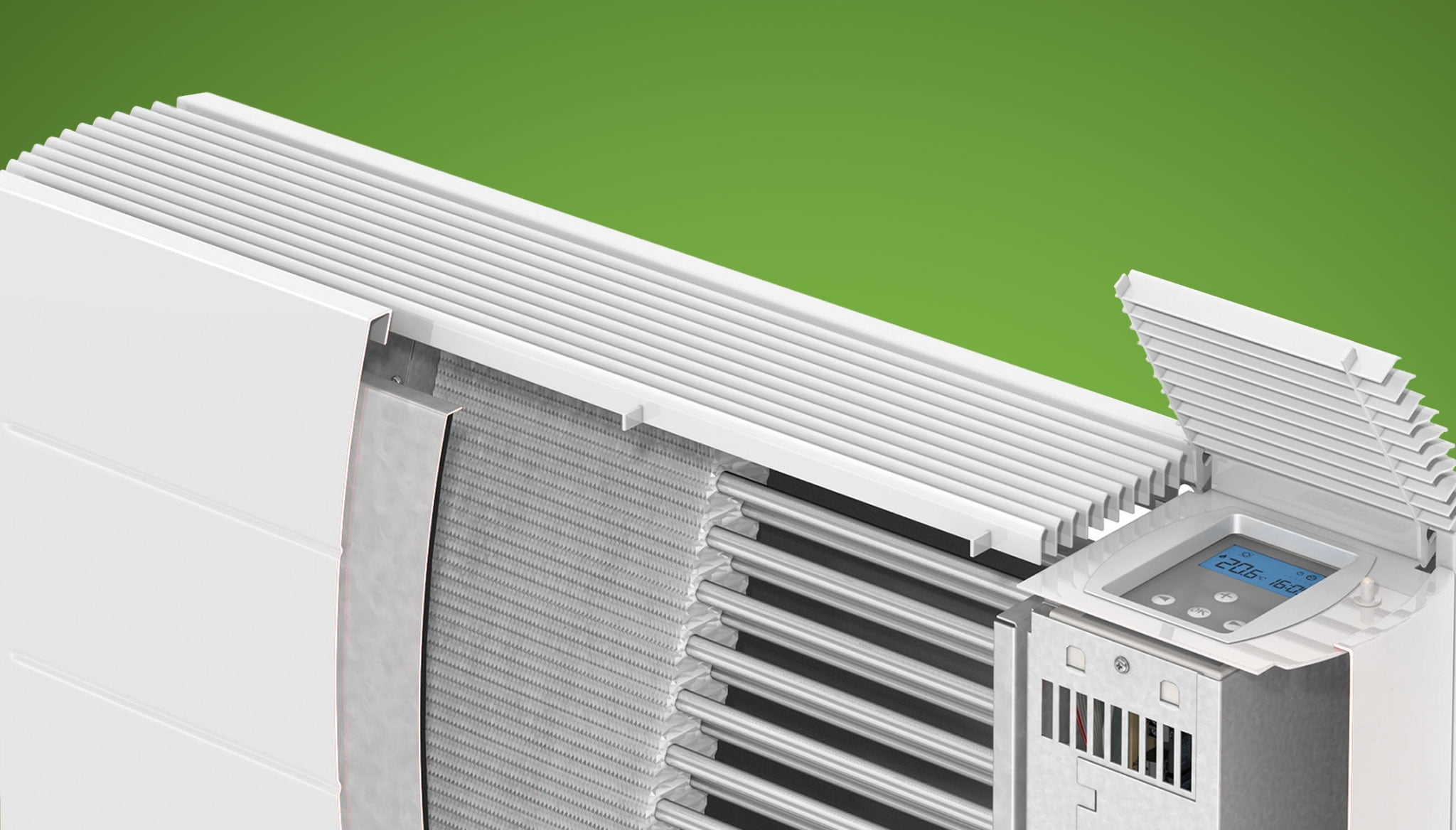
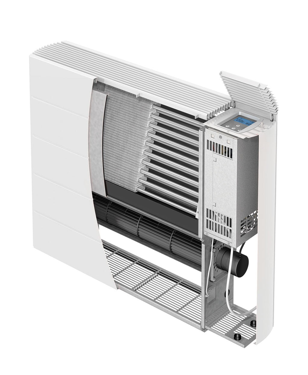
There are also several types of fan-coils and small air handlers that can operate with chilled water to produce cooled and dehumidified air. Some are “console” fan-coils, such as the unit shown in Figure 1.
ENLARGE
FIGURE 1
Console fan-coils are mounted low on walls, and typically sized on a room-by-room basis. Modern console fan-coils have a low-wattage ECM-powered tangential blower that creates even air flow air across a coil. As the warm, humid air passes through the coil, it is cooled and dehumidified. The water removed from the incoming air stream condenses on the coil and eventually drips off it. It is essential for any console fan-coil being used with chilled water to be equipped with a condensate drip pan. Not all console fan-coils are so equipped.
The drip pan must be connected to a condensate drain pipe. Codes vary on where the condensate drain pipe can go. Some allow it to be connected to the building’s DVW piping. Others may specifically prohibit this. I prefer to keep condensate drains separated from other draining systems. Terminating them just above a basement floor drain is one option. Running them outside the building, such as through a soffit, is another. Even small console fan coils can produce several gallons of condensate when the system is operating on a muggy day. Console fan-coils can also be used for heating when supplied with warm water.
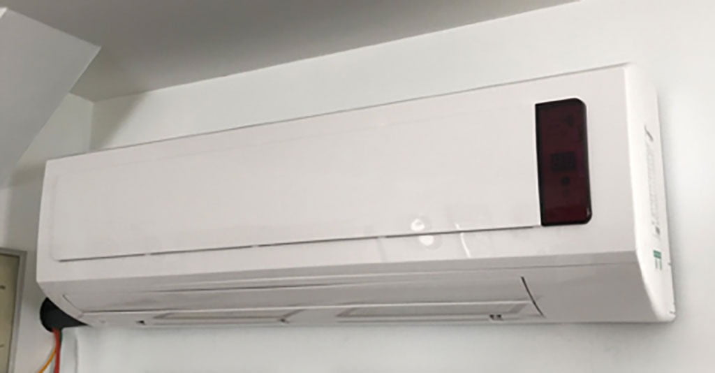
Another type of fan-coil is often called a “high wall cassette.” An example is shown in Figure 2.
ENLARGE
FIGURE 2
These units are very similar to the cassettes used in ductless mini-split heat pump systems. Their internal coils are designed for water rather than refrigerant. They’re available with total cooling capacity ranging from about 6,000 to 24,000 Btu/h (0.5 to 2 tons). Most of these units have a variable-speed high-efficiency blower, oscillating discharge air dampers and a handheld remote control for setting operating modes. These units can also be used for heating.
The next step up is one or more air handlers. The idea is the same as with a fan-coil, with the difference being air delivery through ducting vs. directly from the unit. Chilled water flows through a coil made of copper tubing and aluminum fins. Incoming air is pulled across this coil where it’s cooled and dehumidified on its way to the inlet of a blower. That blower then drives the conditioned air through a duct system to multiple registers or diffusers.
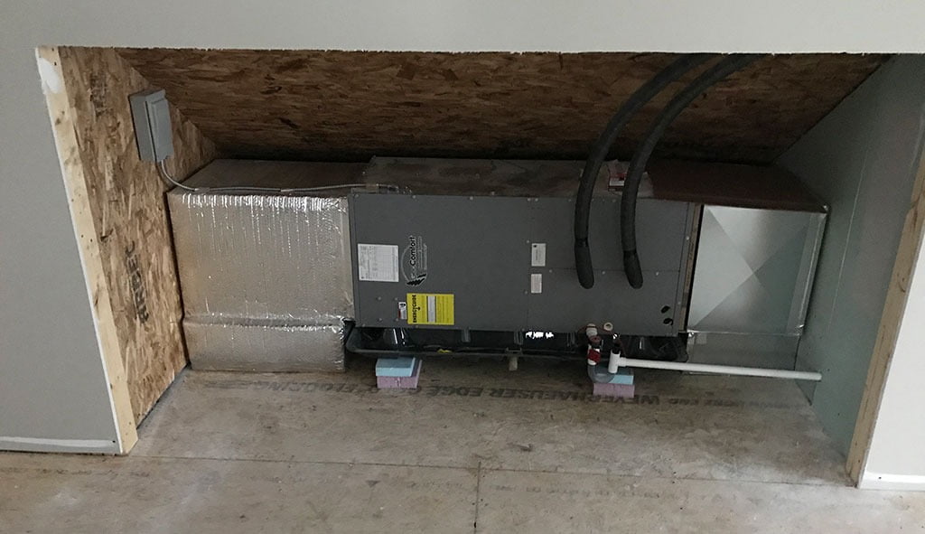
Most air handlers, such as the unit shown in Figure 3, are designed to be installed out of sight.
ENLARGE
FIGURE 3
Vertical air handlers can be mounted in basements, closets, under stairs or in other accessible spaces. Horizontal air handlers can be hung from floor framing in a basement or mounted on platforms in attics or above door height in large closets. Many small air handlers can be configured for either vertical or horizontal mounting with minimal field work.
The location of air handlers must provide accessibility for routine maintenance, such as filter changers or other service work. It’s good practice to ensure that the entire air handler, could, if ever necessary, be removed from it mounting location without sawing walls, framing or having to take the air handler apart. The opening in the wall — seen in Figure 3 — will eventually be covered with a small bookcase mounted on rollers, allowing easy access the air handler.
The air handler in Figure 3 is supplied by a pair of 3/4-inch pre-insulated PEX tubes. Pre-insulated oxygen barrier PEX tubing is available in nominal pipe sizes ranging from 1/2-inch to 2-inch, and in coil lengths up to 100 feet, as shown in Figure 4. Its use expedites installation and reduces the possibility of gaps between smaller pieces of insulation.
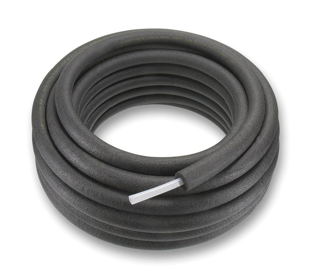
ENLARGE
FIGURE 4
The condensate drain pan inside the air handler of Figure 3 is connected to a 3/4-inch PVC drain pipe that routes the condensate outside or to a drain line within the building. That pipe must have a water-filled condensate P-trap to prevent the blower from sucking air or sewer gases into the air stream. Figure 5 shows how a typical P-trap is typically installed.
ENLARGE
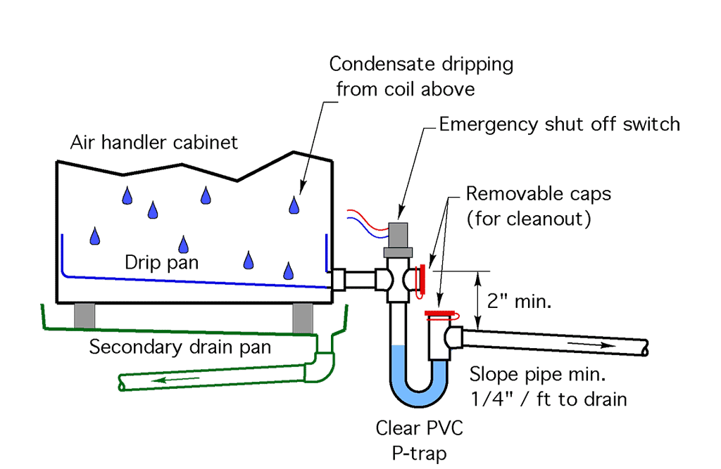
FIGURE 5
Several companies offer complete P-trap assemblies for air handlers. They are typically supplied with a flexible brush that can be used to clean the inside of the trap at the end of each cooling season. Some condensate P-trap assemblies are available with an emergency shutoff switch than can detect if the water level in the P-trap rises above normal due to a clog, and is wired to interrupt operation of the chilled water circuit supplying the air handler.
When an air handler is mounted above finished surfaces, such as drywall surfaces, I prefer to set it into a secondary drain pan, such as seen under the air handler in Figure 3 and in the illustration of Figure 5. This molded plastic pan would serve as a catch basin for condensate if the primary condensate drip pan within the air handler ever developed a leak. The secondary drain pan usually connects to the same condensate drainage pipe as the drain pan in the air handler, and downstream of the P-trap.
Other details
There are several other details that should be included in small-scale chilled water cooling systems.
Be sure that all piping and piping components carrying chilled water are insulated, and that the insulation is vapor sealed. This is critical in preventing surface condensation on the piping and other components. All seams and joints in the insulation should be glued or otherwise bonded to ensure that moisture-laden air can’t contact the piping. Acceptable insulations are elastomeric foam or fiberglass, provided the latter is wrapped with a sealed PVC jacket. Don’t try to “cheat” on pipe insulation or vapor barriers. It only takes a few hours of operation on a humid day to lay down an ugly and costly water stain on drywall ceilings.
Some components such as circulator volutes and valves don’t lend themselves to cylindrical insulation. They still need to be dealt with. A flexible elastomeric self-adhering tape is one possibility. Another is to purchase elastomeric foam in sheets and carefully cut out shapes to fit each component. This custom cutting can then be joined with insulation adhesive. A high-quality electrical tape can also be used to “jacket” pieced insulation assemblies.Don’t oversize the coil in the air handler. Oversized coils will quickly drop the air temperature in a space and satisfy the room temperature setting without allowing sufficient time for adequate moisture removal. The result will be cool but “clammy” air. When possible, I suggest selecting a coil that can meet the latent (moisture removal) and sensible cooling load when supplied with 50° to 55° chilled water. This improves the cooling performance and energy efficiency ratio (EER) of the heat pump relative to its performance at a 45° chilled water supply temperature.
If you’re planning a zoned cooling system with multiple fan-coils or air handlers and supplying them from a fixed-speed heat pump, be sure to include a buffer tank. A 2-ton air handler supplied by a 4-ton heat pump without a buffer tank will quickly drop the water temperature to the point where the heat pump turns off on its own internal temperature or pressure limit. This is necessary to prevent the water from freezing inside the chiller and possibility rupturing piping.
Make provisions with owners to clean the drip pans in all fan-coils and air-handlers at the end of the cooling season. There are several biocides on the market formulated to reduce mold growth in drip pans, but they’re not a substitute for a good cleaning with detergent followed by a wipe down.
Set up the expansion tank for a slightly lower air pressure so some water remains in the tank at room temperature. The goal is to prevent the diaphragm from “bottoming-out” against the tank shell when the system is operating with chilled water. This is especially important in systems with buffer tanks. The greater the system volume, the more “shrinkage” as the water cools well below room temperature. If the diaphragm bottoms out against the shell of the expansion tank, the pressure in some parts of the system could drop to sub-atmospheric and cause air to be sucked into the system through vents.
It’s coming to you
The strong interest in replacing fossil-fuel heat sources with electrically driven heat pumps makes it likely that small-scale chilled water cooling with see increasing use. This is — and will continue to be — a favorable “disruptor” to the traditional market for residential hydronic systems (e.g., heating only systems). Hydronics technology professionals need to recognize this change in the global energy market, and be ready with solutions that will allow them to profit from it.

Feature photo and Figure 1 courtesy of Myson. Figure 4 courtesy of Uponor. Figures 2, 3 & 5 courtesy of John Siegenthaler.
John Siegenthaler, P.E., is a consulting engineer and principal of Appropriate Designs in Holland Patent, New York. His latest textbook, “Heating with Renewable Energy,” was released in January 2017 from Cengage Publishing.