One shot after another
The Glitch:
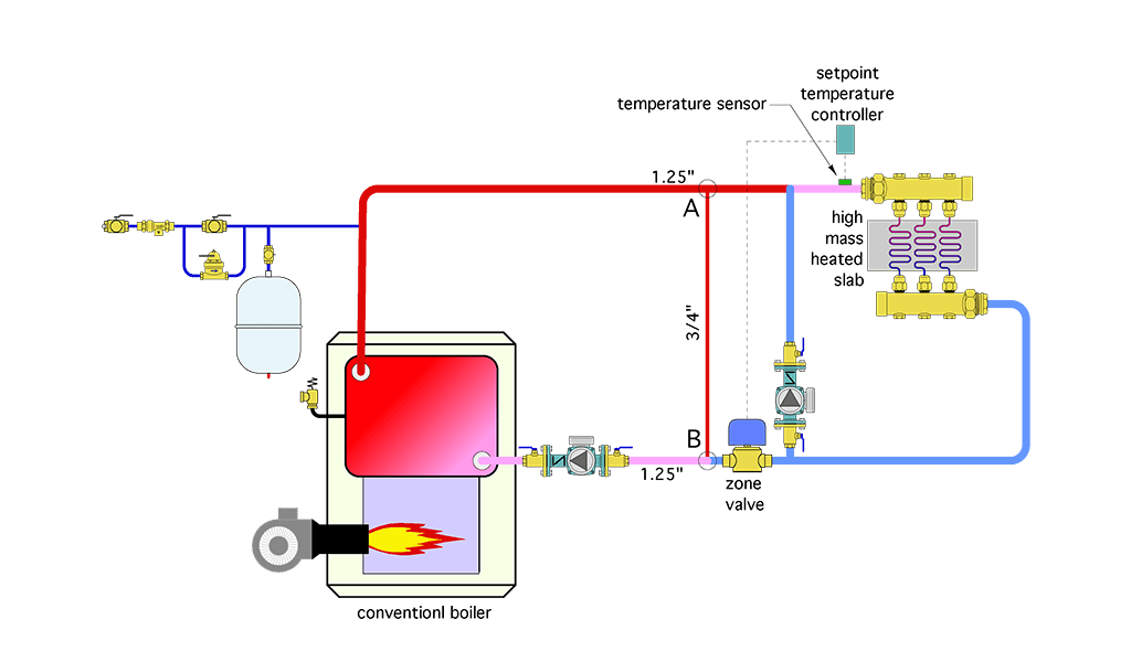
A technician encounters a system installed in the 1980s when radiant floor heating was relatively new in North America. The layout of that system is shown in Figure 1.
The temperature of water supplied to a radiant floor slab is controlled by sending repeated “pulses” of hot water into a circulating loop that supplies three embedded circuits. When the temperature at a sensor on the supply manifold reaches a setpoint, the zone valve closes. The radiant loop circulator continues to operate, allowing the temperature in the floor circuits to “coast” downward. When the temperature controller senses a drop of 10° F at the supply manifold, the zone valve reopens. The original installer purposely reduced the size of the piping between points A and B from 1 1/4-inch to 3/4-inch piping to induce a pressure differential that drives hot water from the boiler into the lower temperature portion of the system when the zone valve is open.
Can you identify some shortcomings of this system and suggest some improvements?
ENLARGE

Are you an ace troubleshooter?
Within the pages of this magazine, PM’s Hydronics Editor John Siegenthaler, P.E., will pose a question to you, our readers, to review a system’s schematic layout and discover its faults, flaws and defects. Discover archived “The Glitch & The Fix” exercises at its radiant-focused website, www.radiantandhydronics.com. Good luck!
