Cut & Cap
The Glitch:
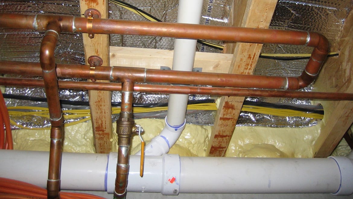
Take a look at the piping in figure 1.
ENLARGE
FIGURE 1
The horizontal piping is the end of a “boiler loop” assembled with 1” copper tubing and fastened to the underside of floor framing.
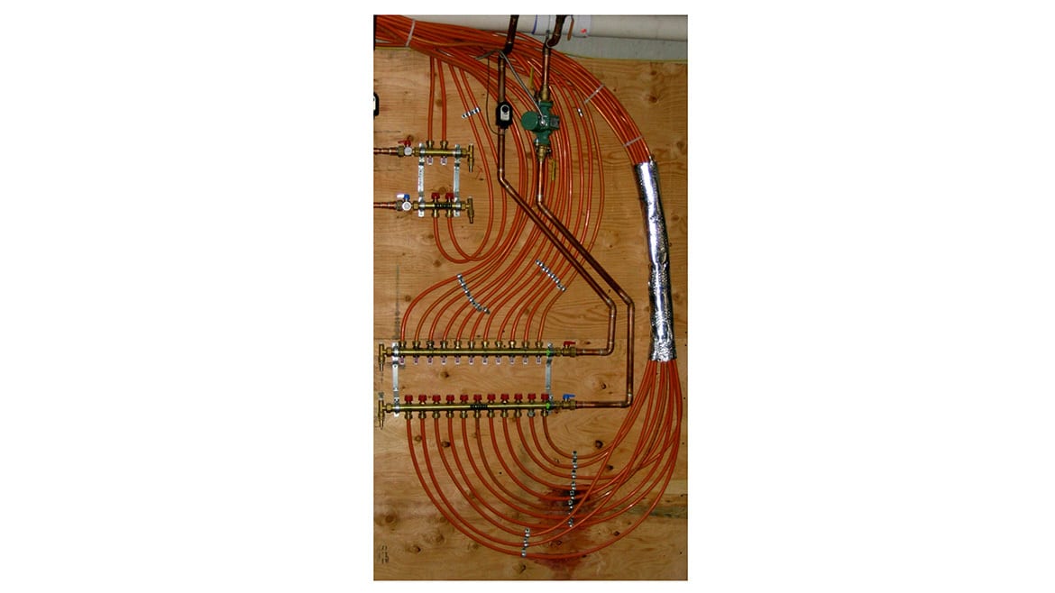
Figure 2 shows the 3/4” copper tubing that tees into that boiler loop going down to a manifold station. The pipe on the right passes through a ball valve, then down through a circulator. The pipe on the left passes up through a zone valve.
ENLARGE
FIGURE 2
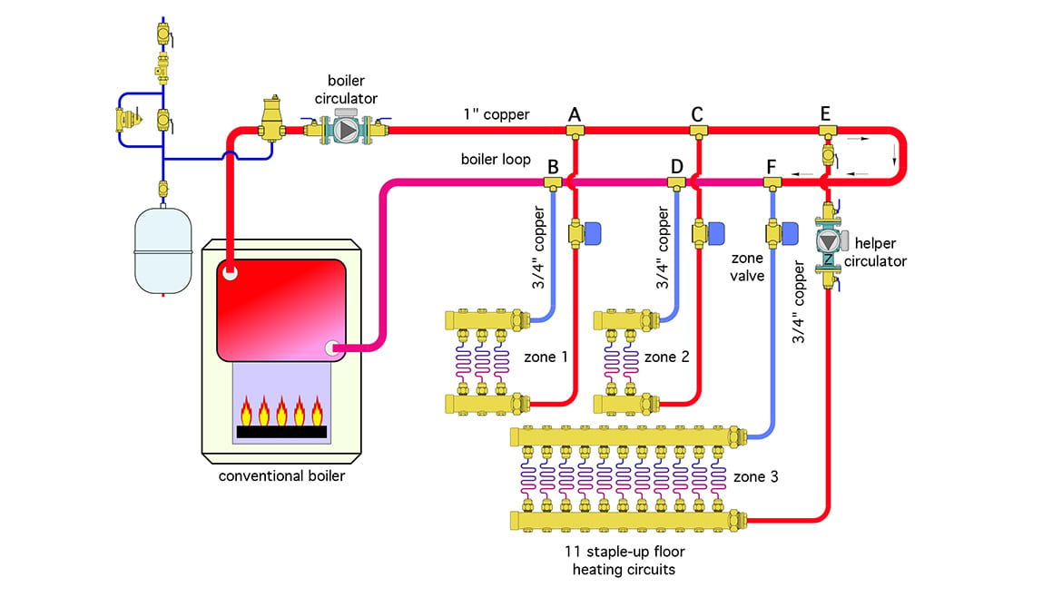
Figure 3 is a partial schematic of the overall system.
ENLARGE
FIGURE 3
The “intent” for this system was three independently controlled zones. The boiler circulator was set up to run when any zone valve opens.
Zones 1 and 2 provided adequate comfort, but zone 3 did not. In an attempt to remedy the situation, the installer returned and added a “helper circulator” in zone 3 that operates along with the zone valve.
Can you speculate why heat delivery in zone 3 was insufficient prior to the helper pump? Can you come up with a better way to pipe this system? Try to look past the waste of a couple hundred feet of PEX-AL-PEX tubing leading from the manifold stations up to the floor panels in figure 2 as you think about how to rework the system.
Are you an ace troubleshooter?
Within the pages of this magazine, PM’s Hydronics Editor John Siegenthaler, P.E., will pose a question to you, our readers, to review a system’s schematic layout and discover its faults, flaws and defects. Discover archived “The Glitch & The Fix” exercises at its radiant-focused website, www.radiantandhydronics.com. Good luck!