
CODES CORNER
BY TAYLOR COSTEA
An introduction to IAPMO IS 34
This comprehensive document serves as the first illustrative manual of its kind in the nation.

IAPMO has collaborated with the National Electrical Contractors Association (NECA) and the Los Angeles Department of Water and Power (LADWP) to produce an installation standard for solar photovoltaic (PV) and energy storage systems (ESS) in residential applications. This collaboration resulted in the development of IAPMO IS 34 (Installation Standard for Residential Solar Photovoltaic and Energy Storage Systems) which addresses the most relevant and comprehensive provisional language for the installation of these systems.
IAPMO IS 34 addresses plan details, electrical requirements and calculations, roof mounted panels, ground-mounted arrays, marking and labeling, and product safety standards for PV equipment. Annexes were created to provide additional information pertaining to size and optimization of solar photovoltaic with energy storage systems (PV-ESS), best practices for electrical work safety, smart solar monitoring technology and sample site plans for various residential PV and PV-ESS. This comprehensive document serves as the first illustrative manual of its kind in the nation. The IS 34 Installation Standard was generated by a committee of experts in the installation and inspection of solar PV systems including: LADWP, NECA, Aztec Solar, Sunrun, CSULA, SunEarth, Sound Geothermal, Donald F. Dickerson Associates, ASHRAE and Southern California Pipe Trades Council.
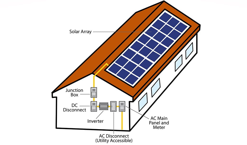
To give users an insight as to how solar PV systems function, figures on solar PV systems were incorporated into the standard. As shown in Figure 1, solar PV panels are installed in rows where each row is considered to be on a string.
ENLARGE
FIGURE 1
Solar PV System — DC String Inverter.
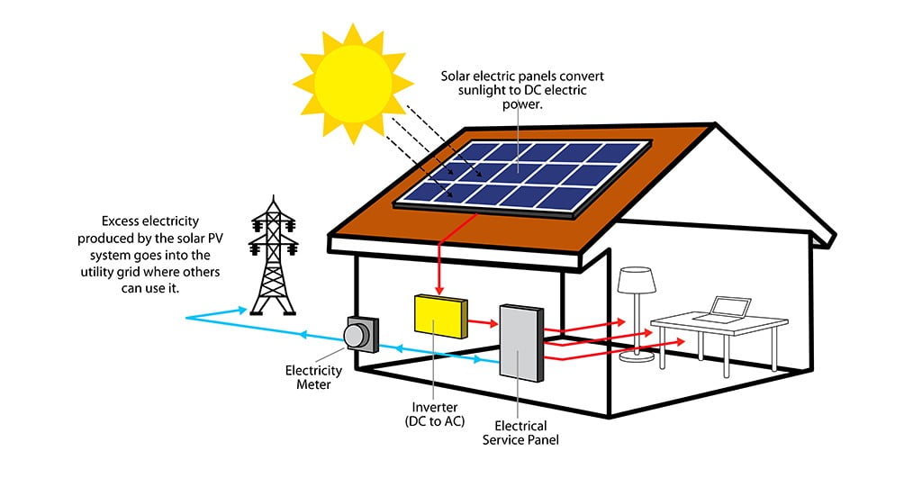
There are various other configurations where multiple rows of strings are combined and connected to a single string inverter. These strings carry the direct-current produced by the solar PV panel to the string inverter where it is converted to alternating-current. This flow of energy and conversion for residential use also includes connection to the utility grid as reflected in Figure 2 and Figure 3.
ENLARGE
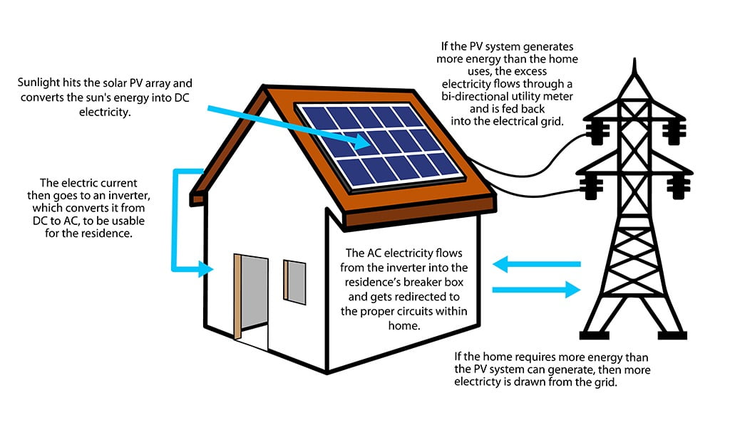
FIGURE 2
Solar PV System — Power Distribution.
ENLARGE
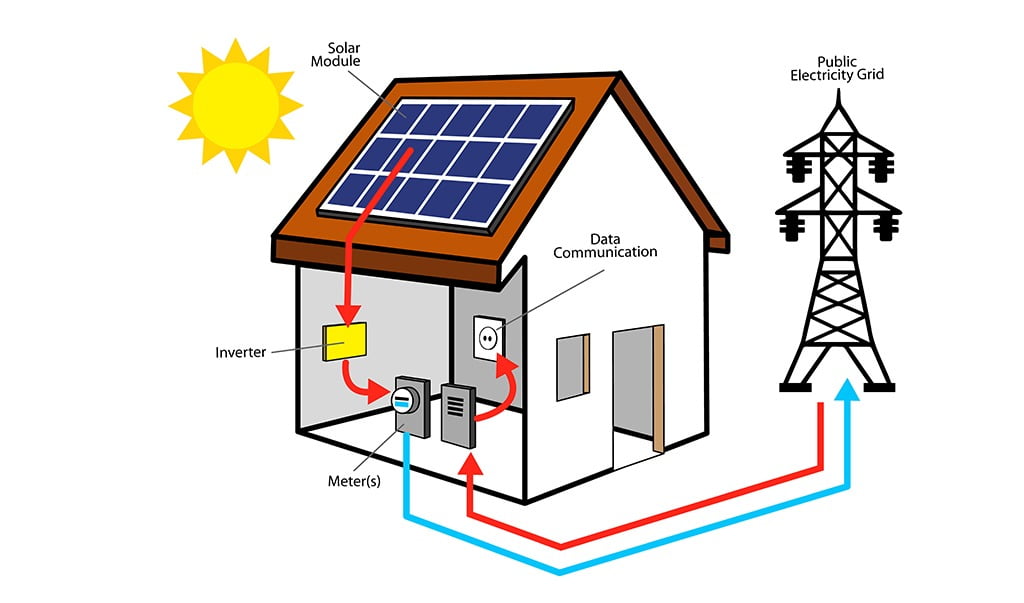
FIGURE 3
Solar PV System — Utility Demand Response.
For periods where the solar PV panels do not generate sufficient electricity to meet the demand, the power is supplied by the public electricity grid.
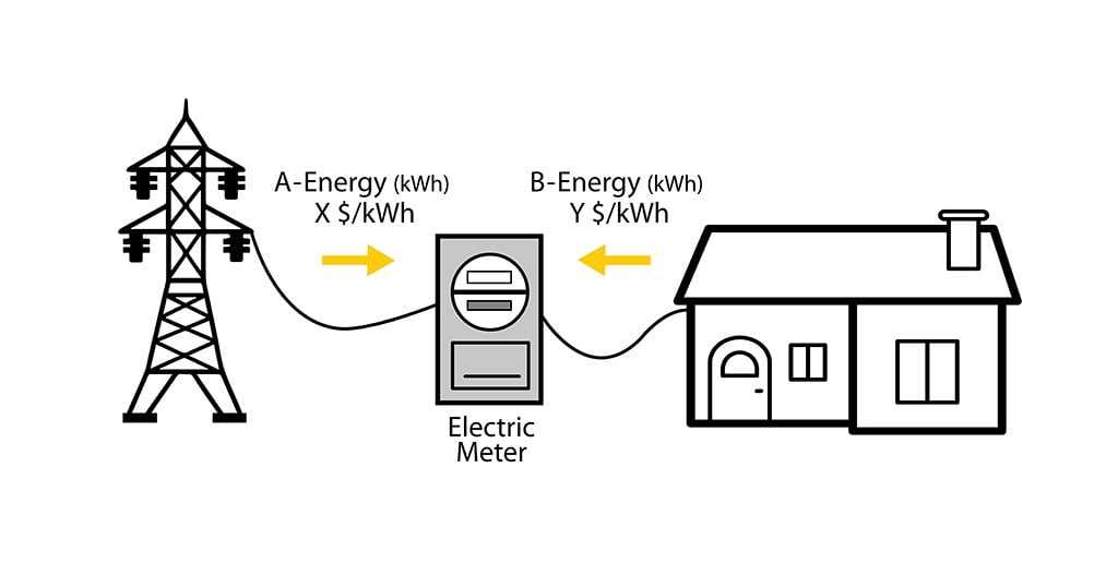
As a result of this power distribution and utility demand response, smart solar monitoring technology is commonly installed in tandem with these systems and serve as energy saving tools. Such technology includes net energy metering and smart meters which both have the potential to influence changes in energy conservation behaviors. As depicted in Figure 4 and Annex C (Smart Solar Monitoring Technology) of IAPMO IS 34, net energy metering uses a bi-directional meter (e.g. analog, electro-mechanical, smart, radio frequency, etc.) to measure the energy difference between the amount supplied by the utility grid and the amount the utility grid receives from user generation.
ENLARGE
FIGURE 4
Net Energy Flow Diagram.
These bi-directional meters are then used to facilitate the net energy metering process depicted in Figure 5.
ENLARGE
FIGURE 5
Solar PV System — NEM Process (Simplified).
Smart meters, however, serve a different purpose for solar PV systems in that they provide a means of measuring electrical consumption in real-time rather than only measuring the total consumption. This allows for more accurate measurements and improved management of energy usage.
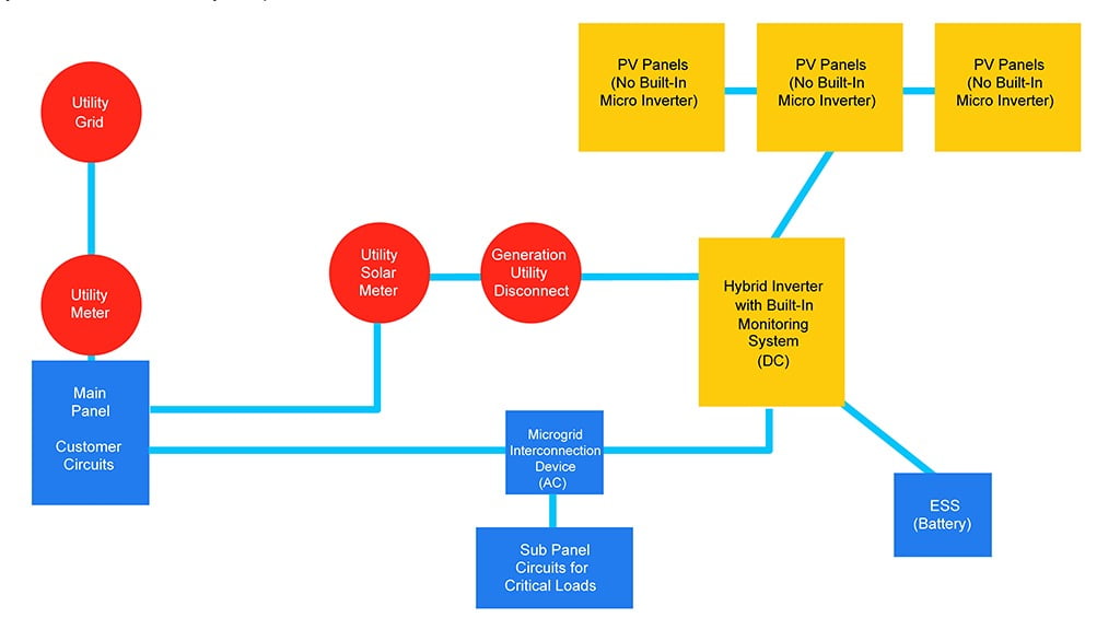
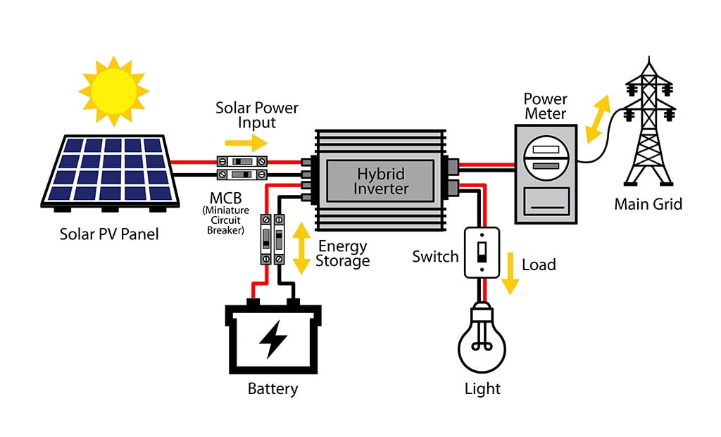
In addition to smart solar monitoring technology, ESS may be installed and used to collect energy, charging during peak sunlight hours, and then supplying that energy at night when the PV system generates minimal to no electricity. ESS are commonly installed in combination with renewable energy systems to increase the efficiency and effectiveness of the overall systems. Plan details for ESS can be found in IAPMO IS 34 along with figures which concentrate on PV-ESS components, functioning and optimization. One representation of a residential PV-ESS can be seen in Figure 6 where common system components are listed in a simplified configuration. This line diagram depicts the connections required between the panels, inverter, microinverter, ESS and the utility.
ENLARGE
FIGURE 6
Typical Components of a PV-ESS (Simplified)
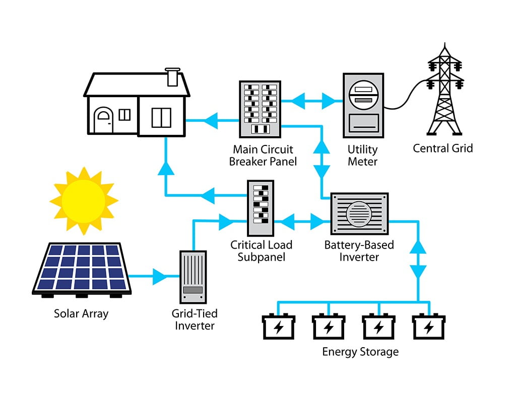
In order to provide users with energy flow diagrams for PV-ESS, Figure 7 through Figure 9 were generated. Figure 7 and Figure 8 are included in the standard to show PV-ESS configurations in which electricity is exported to the utility grid. In Figure 7, the PV-ESS configuration requires two inverters, both grid-tied and battery-based, since both the solar array and battery are connected to the critical load subpanel. In addition, the battery-based inverter flows electricity through the main circuit panel before connection to the utility meter.
ENLARGE
FIGURE 7
PV + AC-Coupled ESS Configuration with Grid Export Line Diagram (Simplified)

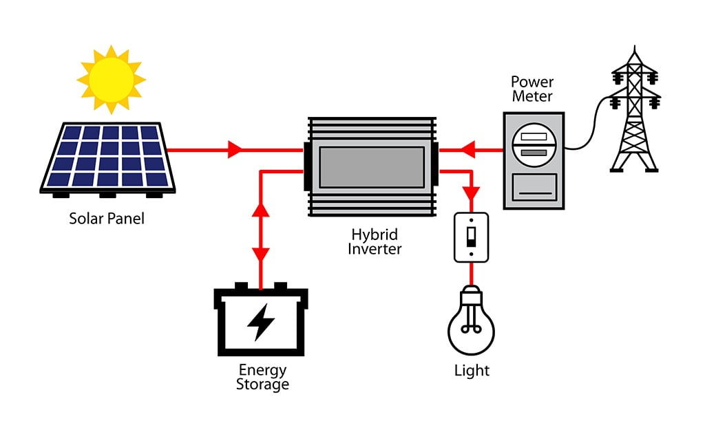
On the contrary, Figure 8 and Figure 9 display a flow diagram where both the solar array and ESS are connected to the same inverter. As shown, these hybrid inverters are usable for configurations with or without grid export. These figures and flow diagrams only represent a few possible PV-ESS configurations. Equipment arrangements and configurations often vary based on design.
ENLARGE
FIGURE 8
PV + DC-Coupled ESS Configuration without Grid Export (Simplified).
ENLARGE
FIGURE 9
PV + DC-Coupled ESS Configuration with Grid Export (Simplified).
One of the most innovative concepts listed in IAPMO IS 34 can be found in Annex A (Size Optimization and Operation of PV-ESS) where a layout or roadmap of a PV-ESS hierarchical control system is provided. (See Figure 10.) This layout includes both high- and low-level planning algorithms to make prediction models which find the most optimal operation strategies and concurrently adjust for changing user goals and restrictions. Since ESS is utilized for load shifting rather than power generation, the specific goals of the system as well as the various constraints must be identified and considered when implementing this type of control system. For a more detailed description of this predictive hierarchical control system, please refer to IAPMO IS 34.
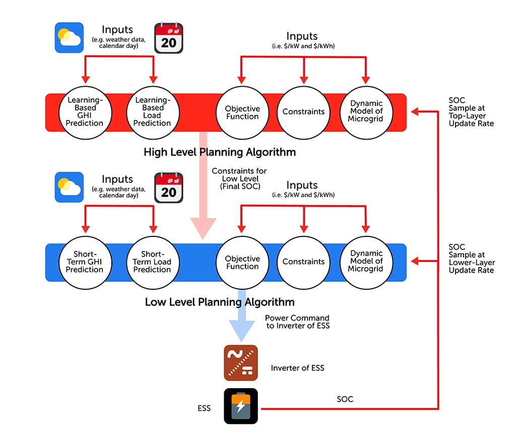
ENLARGE
FIGURE 10
Layout for Predictive Hierarchical Control System
These discussed figures, along with various pathway and setback figures for roof PV panel installations, make IAPMO IS 34 a universal guide for all users ranging from those who simply desire to learn about solar PV systems to well-trained installers. As public safety is a priority of IAPMO, a list of best practices for electrical work safety is also included within the standard. IAPMO strives to provide leading nationally recognized installation standards, and this comprehensive document is no exception. Visit http://bit.ly/2PSU4MX to purchase a copy of the IS 34 (Installation Standard for Residential Solar Photovoltaic and Energy Storage Systems). The IS 34 Installation Standards is also included as part of the 2021 Uniform Solar, Hydronics, and Geothermal Code (USHGC), which was published in February.

anatoliy_gleb/iStock / Getty Images Plus via Getty Images
Taylor Costea is a technical code administrator for IAPMO. In her role, she works on the development of the Uniform Solar, Hydronics and Geothermal Code (USHGC) as well as the Uniform Swimming Pool, Spa and Hot Tub Code (USPSHTC). Costea has a bachelor’s degree in mechanical engineering from California State University Los Angeles and is an Engineer in Training (E.I.T.) for the State of California.